Projection display unit

a technology of projection display and display unit, which is applied in the direction of picture reproducers, picture reproducers using projection devices, instruments, etc., can solve the problems of dynamic range and optical utilization efficiency degradation, and achieve the suppression of optical utilization efficiency deterioration, high dynamic range, and high dynamic range

Active Publication Date: 2022-04-12
SONY CORP
View PDF21 Cites 0 Cited by
  • Summary
  • Abstract
  • Description
  • Claims
  • Application Information

AI Technical Summary

Benefits of technology

[0007]It is therefore desirable to provide a projection display unit that achieves the high dynamic range while suppressing deterioration in the optical utilization efficiency.
[0010]According to the projection display unit of the embodiment of the technology, the second light and the light passing through the first spatial light modulator enter the integrator optical system, which makes it possible to selectively form only the high-luminance region using the first spatial light modulator, and to maintain the luminance in a portion other than the high-luminance region. This makes it possible to achieve the high dynamic range in the high-luminance region, as well as to suppress deterioration in the optical utilization efficiency in the portion other than the high-luminance region. It is to be noted that the effects described here are not necessarily limitative, and the effects of the technology may be any of the effects that will be described herein.

Problems solved by technology

However, an increase in the dynamic range causes deterioration in optical utilization efficiency.

Method used


Image

  • Projection display unit
  • Projection display unit
  • Projection display unit

Examples


embodiment

(Configuration)

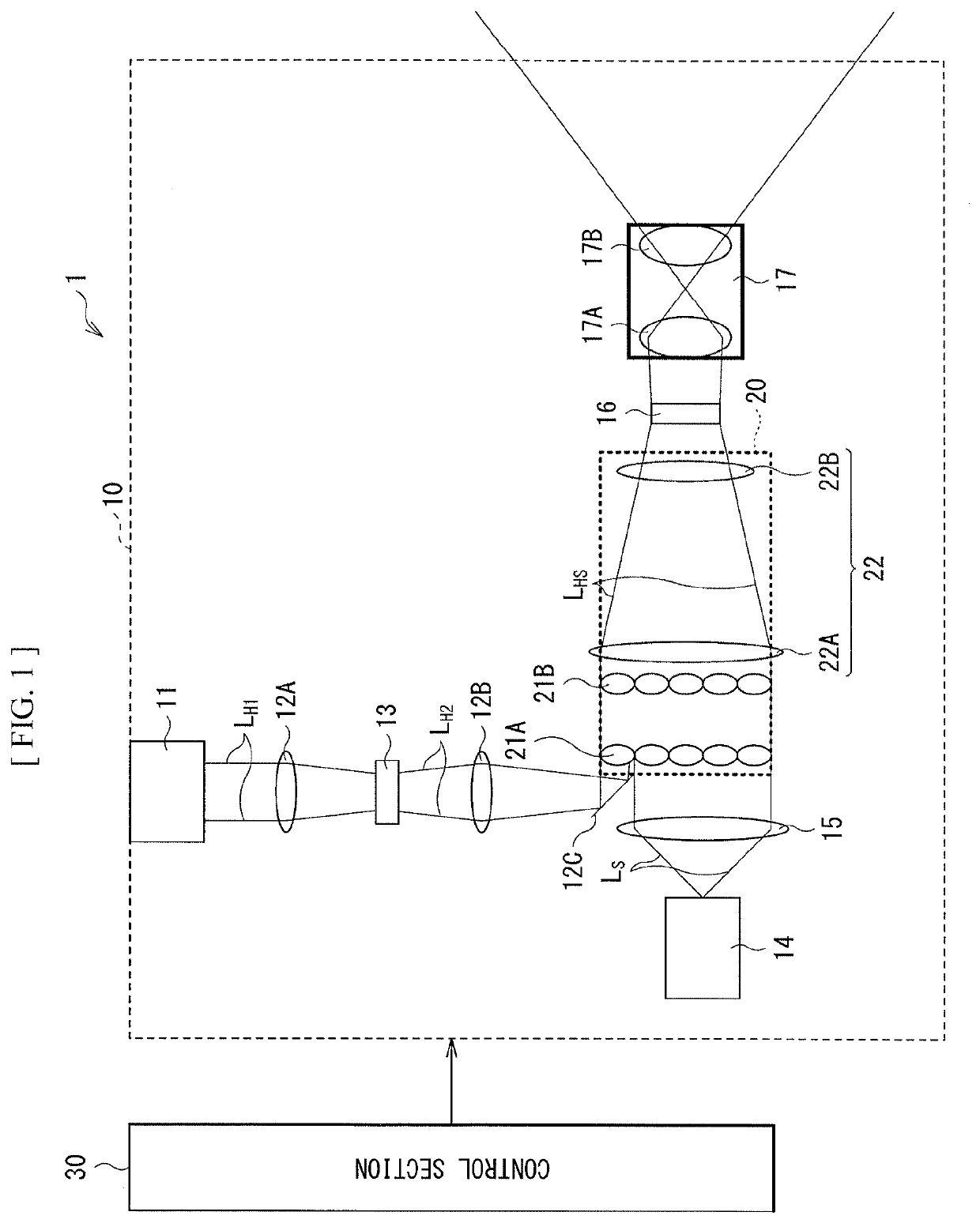
[0031]FIG. 1 is a schematic view of an overall configuration of a projection display unit (a projection display unit 1) according to an embodiment of the technology. The projection display unit 1 is, for example, a display unit that projects images on a screen. The projection display unit 1 is coupled to an external image supply apparatus including, for example, a computer such as a PC, or various image players, etc. through an IT (interface), and carries out image projection on a screen on the basis of image signals incoming into the I / F. It is to be noted that a configuration of the projection display unit 1 to be described below is illustrative only, and the projection display unit of the technology is not limited to such a configuration.

[0032]The projection display unit 1 includes an optical section 10, and a control section 30 that controls operation of the optical section 10. The optical section 10 includes a first light source 11 and a second light source 14, a...

modification example 1

[0055]FIG. 5 schematically illustrates an overall configuration of a projection display unit (a projection display unit 1A) according to a modification example 1. The projection display unit 1A has a first spatial light modulator 73 in place of the first spatial light modulator 13 in the above-described embodiment. The first spatial light modulator 73 carries out phase modulation. In this respect, the projection display unit 1A differs from the projection display unit 1.

[0056]The first spatial light modulator 73 includes, for example, a liquid crystal panel or a mirror device. The first spatial light modulator 73 performs the phase modulation for the HDR light LH1 that is emitted from the first light source 11 to pass through the first illumination optical system 12A. From the first spatial light modulator 73, phase-modulated diffracted light LH3 is outputted. As with the first spatial light modulator 13, the first spatial light modulator 73 is provided at an optical path between th...

modification example 2

[0059]FIG. 6 schematically illustrates a configuration of an optical section 10 of a projection display unit (a projection display unit 1B) according to a modification example 2. The projection display unit 1B has an integrator optical system 40 that includes a rod integrator 41 in place of the integrator optical system 20 in the above-described embodiment. In this respect, the projection display unit 1B differs from the projection display unit 1.

[0060]The integrator optical system 40 includes, for example, the rod integrator 41 and the fourth illumination optical system 22. For example, the rod integrator 41, the first lens 22A, and the second lens 22B are disposed in this order from the side that the light from the second illumination optical system 12B and the third illumination optical system 15 (the HDR light LH2 and the SDR light LS) enters. The rod integrator 41 includes, for example, a glass rod having a cylindrical shape or a prismatic shape such as a quadrangular prism. Wh...


PUM


Abstract

A projection display unit includes a first spatial light modulator that first light enters; and an integrator optical system that second light and light passing through the first spatial light modulator enter.

Description

CROSS REFERENCE TO RELATED APPLICATIONS[0001]This application is a national stage application under 35 U.S.C. 371 and claims the benefit of PCT Application No. PCT / JP2017 / 021798 having an international filing date of 13 Jun. 2017, which designated the United States, which PCT application claimed the benefit of Japanese Patent Application No. 2016-151709 filed 2 Aug. 2016, the entire disclosures of each of which are incorporated herein by reference.TECHNICAL FIELD[0002]The technology relates to a projection display unit that makes it possible to achieve an HDR (High Dynamic Range).BACKGROUND ART[0003]In recent years, in the field of image display, technologies of enhancing a dynamic range have been proposed (for example, see PTLs 1 and 2), and in particular an HDR has attracted attention. The HDR refers to expanded gray-scale representation of a low-luminance portion, or an image signal format of high peak luminance. Hitherto, luminance representation as high as 100 cd / m2 has been ac...

Claims


Application Information

Patent Timeline
Patent Type & Authority Patents(United States)
IPC IPC(8): G03B21/00H04N9/31G02B3/00G03B21/14G02B13/16G03B21/20G03B33/12
CPCH04N9/3182G02B3/00G02B13/16G03B21/005G03B21/14G03B21/2013G03B33/12H04N9/3126H04N9/3138H04N9/3164
Inventor SATO, YOSHIHISA
Owner SONY CORP
Why Eureka
Try Eureka