Adjustable shelving

a shelving and adjustable technology, applied in the field of racks, can solve the problems of complex wire forms and configurations, and the construction of the majority of rack structures is relatively complex, and achieve the effect of less heigh

Active Publication Date: 2018-10-09
LINARI RONALD +1
View PDF34 Cites 11 Cited by
  • Summary
  • Abstract
  • Description
  • Claims
  • Application Information

AI Technical Summary

Benefits of technology

[0006]In accordance with other aspects of the present invention each shelf has a flat planar middle portion and opposite side portion; each opposite side portion has a c-shaped cross-section; the first shelf is wider than the second shelf in order to accommodate an engagement and sliding between the shelves; each receiving port is at a corner of the shelf and is sized to receive a top of the support leg; each receiving port is at a corner of the shelf and is sized to receive a top of the support leg; each receiving port includes a web that is disposed across the receiving port and upon which a top of the support leg rests; wherein the receiving port is circular, the web is circular and the web is secured within the receiving port to provide an open top port section that is of less height than an open bottom port section; wherein each support leg is comprised of an outer tube and an inner tube that is slideable relative to, concentric, and disposed within the outer tube; wherein the outer tube has a series of holes spacedly disposed along a length of the outer tube, and the inner tube supports a locking button for engagement with any one of the holes in order to adjust the height of the leg; wherein each of the first and second shelves has spaced apart support corners, and the plurality of legs comprise four legs, one engaged with a receiving port that is disposed at each corner of the respective first and second shelves; wherein the first and second shelves have a closed position wherein a total length of the first and second shelves is at a minimum length and an open position wherein the total length of the first and second shelves is longer than the minimum length; including at least a fifth leg for support of the first and second shelves at a location between the shelf corners; including fifth and sixth legs for support of the first and second shelves at a location between the shelf corners; wherein the second shelf has a through hole for receiving a top end of the fifth leg, or wherein the second shelf has a pair of spaced apart through holes for receiving a top end of the respective fifth and sixth legs; including spaced apart holes that extend longitudinally of the second shelf so as to be able to support the first and second shelves at different extended positions therebetween.

Problems solved by technology

Most of these rack structures are relatively complex in construction and, in particular, for a shoe rack, require complex wire forms and configurations.

Method used


Image

  • Adjustable shelving
  • Adjustable shelving
  • Adjustable shelving

Examples


first embodiment

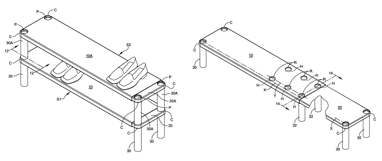
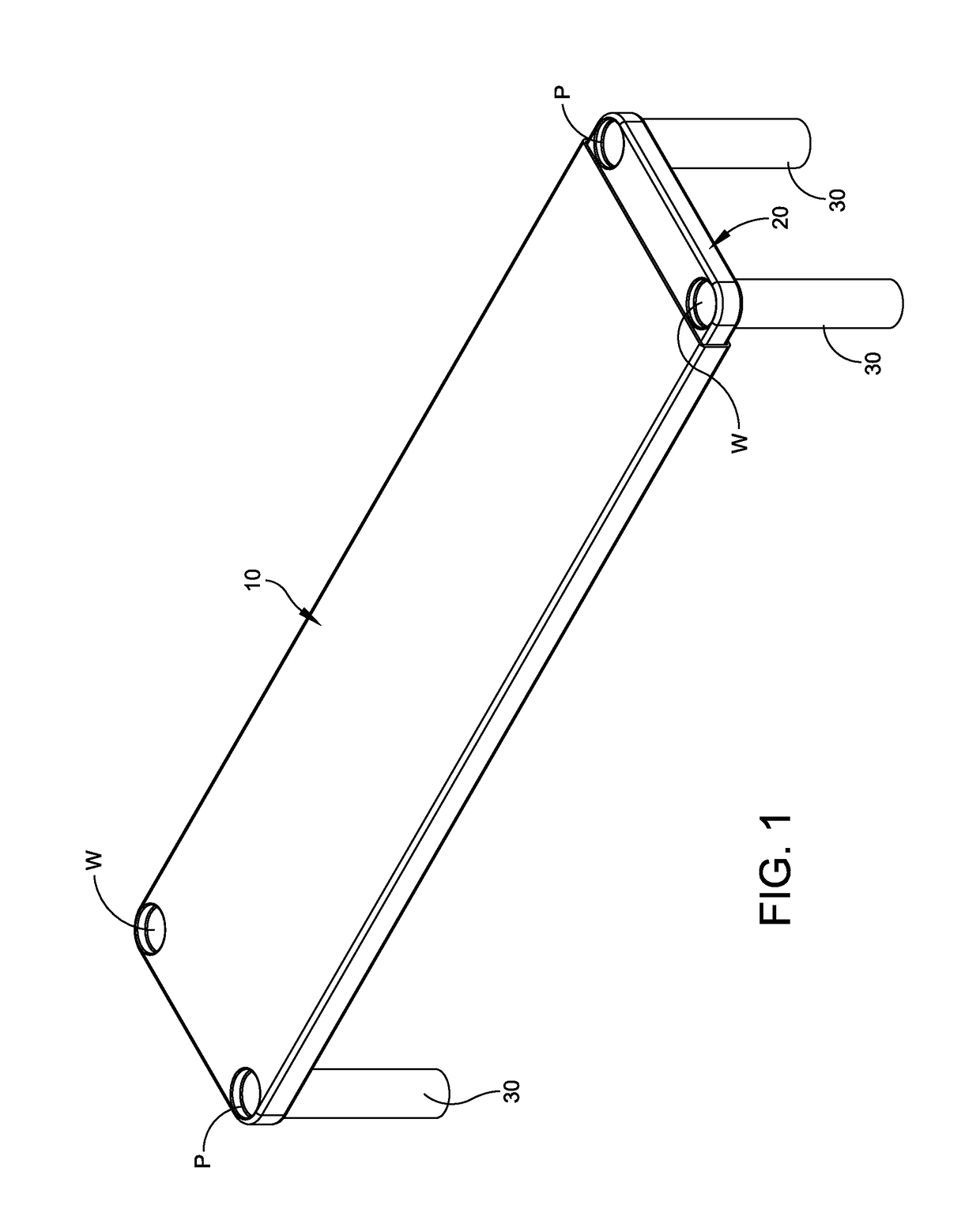
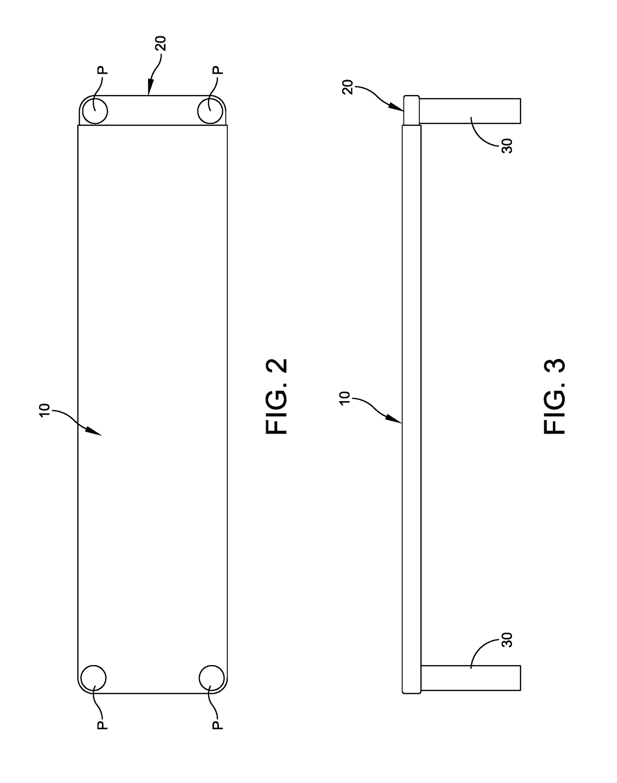
[0044]Reference is now made to the present invention illustrated in FIGS. 1-10. A related embodiment is illustrated in FIGS. 11 and 12. FIGS. 11 and 12 describe the stacking concept of the present invention. FIGS. 13-15 illustrate another feature of the present invention that employs middle support legs. This is particularly advantageous when the two shelves are moved to an extended position, as illustrated in FIG. 13. Finally, FIGS. 16-21 illustrate the use of support legs that are adjustable in height.

[0045]With respect to FIGS. 1-10, the rack, which is for supporting various types of items including shoes, is comprised of a first shelf 10 and a second shelf 20 that slidably interlocks with the first shelf 10. These shelves are supported by means of a plurality of support legs 30. In the illustrated embodiment there are two support legs for each of the first and second shelves. Each of the shelves 10, 20 have one end that includes a pair of spaced apart receiving ports P with each...


PUM

PropertyMeasurementUnit
total lengthaaaaaaaaaa
lengthaaaaaaaaaa
heightaaaaaaaaaa

Abstract

A rack for supporting items and comprising a first shelf and a second shelf that slideably interlocks with the first shelf and a plurality of support legs including at least two support legs for each of the first shelf and second shelf. Each of the first and second shelves has one end that includes a pair of spaced apart receiving ports with each receiving port for accommodating a corresponding support leg. Each of the first and second shelves further has an opposite end with the opposite ends for respective sliding engagement therebetween in order to provide the slideable interlocking.

Description

FIELD OF THE INVENTION[0001]The present invention relates in general to a rack for supporting items, and in particular, a rack that is adjustable. The present invention also relates to a shoe rack that employs separate shelf members that can be slidably interlocked in combination with legs for the shelf members. Even more particularly, the present invention relates to a rack structure that is easy to assemble, that is adjustable at least in height and length, and that is stackable.BACKGROUND OF THE INVENTION[0002]There are various forms of rack structures in the prior art. The rack structure of the present invention is meant primarily for use as a shoe rack. However, it can also be used for the storage of other items. In connection with existing shoe racks, examples can be found in U.S. Pat. No. 4,915,238 to Castle and U.S. Pat. No. 5,065,871 to Chan. Most of these rack structures are relatively complex in construction and, in particular, for a shoe rack, require complex wire forms ...

Claims


Application Information

Patent Timeline
Patent Type & Authority Patents(United States)
IPC IPC(8): A47B47/00A47B45/00A47B57/48A47B61/04A47B87/02A47B96/02A47B87/00
CPCA47B87/0223A47B47/00A47B61/04A47B57/48A47B45/00A47B47/0091
Inventor LINARI, RONALDTREMBLAY, GARY
Owner LINARI RONALD
Why Eureka
Try Eureka