Rotating machine with a fluid supply rotating column

a technology of rotating column and rotating column, which is applied in the field of rotating machines with fluid supply columns, can solve the problems of inability to maintain the column, damage to the electrical commutator, and inability to access the fluid members, etc., and achieve the effect of simplifying its maintenan

Inactive Publication Date: 2011-04-12
SIDEL PARTICIPATIONS SAS
View PDF6 Cites 6 Cited by
  • Summary
  • Abstract
  • Description
  • Claims
  • Application Information

AI Technical Summary

Benefits of technology

There is therefore a pressing demand from users for improvements to be made to the rotating column by simplifying its maintenance, so that the machines would become more efficient and more productive.
It is therefore an object of the invention to provide a rotating supply column with an improved structure that more satisfactorily meets the diverse requirements of the industry, namely a rotating column of less height than in the prior art and on which certain maintenance operations can be carried out easily and quickly, especially the operation of replacing sealing rings between fixed part and moveable part.
Also the actual maintenance, as for example when replacing sealing rings in the rotating column, between the fixed part and the movable part, is of short duration, typically two hours, and can be done in situ, inside the machine, without disconnecting the various leads.
The result is highly ergonomic and easy to assemble and strip, and the parts of the connector are relatively light, compatible with manual work.

Problems solved by technology

However, there are a number of disadvantages inherent in the structure of this known column.
This operation of removing the electrical commutator 10 is time consuming and can result in damage to the electrical commutator 10—even though the commutator 10 is not in need of maintenance.
Furthermore, access to the fluid members is limited.

Method used


Image

  • Rotating machine with a fluid supply rotating column
  • Rotating machine with a fluid supply rotating column
  • Rotating machine with a fluid supply rotating column

Examples


second embodiment

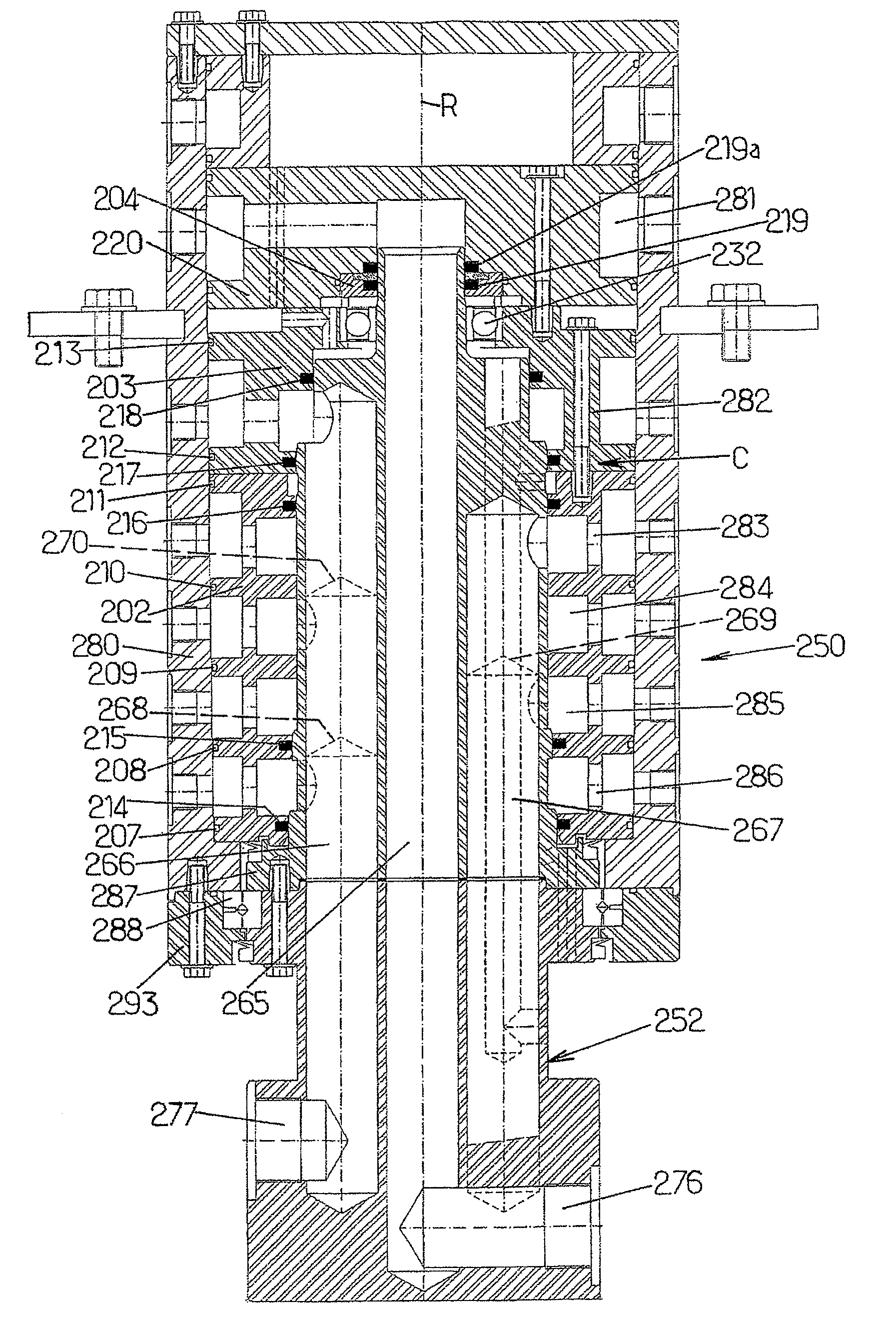
Turning now to FIG. 8, this is a view in longitudinal section through a column element forming a rotating connector according to the invention.

In this second embodiment, the column element 250 comprises a fixed first assembly 252 provided with six axial conduits 265-270 or parallel fluid passage holes, three of these passage holes 265-267 being shown in solid lines in this FIG. 8 while the other three 268-270 appear in dashes in this figure.

These parallel axial conduits 265-270 are of different lengths and each communicate:at the fixed lower part of the element 250, with a radial supply conduit 276-277 (only two radial supply conduits 276-277 are shown in FIG. 8 so as not to overload the figure);at the moveable upper part of the element 250, with radial holes 281-286 located in a given row and passing through a rotating tubular component or tubular body 280, a fixed shaft 287 and a jacket C.

Thus, in much the same way as was described with reference to FIGS. 2 to 7, the first or inne...


PUM

PropertyMeasurementUnit
pressureaaaaaaaaaa
pressureaaaaaaaaaa
pressureaaaaaaaaaa

Abstract

The invention concerns a rotating machine such as a carrousel comprising a rotating frame driven in rotation about an axis of rotation, several working stations supported by the rotating frame, a fluid supplying rotating column, coaxial to the axis of rotation of the rotating frame. The invention is characterized in that it comprises a column element (50, 250) provided with two assemblies (52, 252, 53) mobile in rotation relative to each other, about said axis of rotation, a first assembly (52, 252) including an axial tubular body (80, 280) provided with at least two tiers of radial through holes (81-86, 281-286), the axial conduits of the first assembly (52, 252) extending over different lengths in the space delimited by said tubular body (80, 280), each conduit (65a, 70-73, 75) emerging perpendicularly to one specific tier of radial through holes (81-86, 281-286), the column element (50, 250) thereby defining a rotating connection dispensing at least two fluids towards the working stations of the machine, and in that a sleeve C is interposed between said tubular body (80, 280) of the second assembly (53) and said first assembly (52, 252).

Description

TECHNICAL FILEDThe present invention relates to improvements to carousel-type rotating machines comprising:a rotating frame revolving about an axis of rotation;several workstations supported by the rotating frame;a rotating fluid-supply column coaxial with the axis of rotation of the rotating frame; andat least one rotating fluid connector located on said column and connected to a fixed source of fluid.The invention is more particularly concerned with rotating machines for making containers from thermoplastic materials, such as PET, by blow molding or stretch blow molding a preform (or intermediate container) in molds supported by a rotating bed.The invention can be applied to rotating machines of other types such as filling machines.BACKGROUND OF THE INVENTIONFIG. 1 of the appended drawings shows a side view of a rotating electrical power and fluid supply column currently installed in certain blow molding or stretch blow molding container manufacturing machines built by the applica...

Claims


Application Information

Patent Timeline
Patent Type & Authority Patents(United States)
IPC IPC(8): B29C49/36B29C49/42B29C49/58
CPCB29C49/36B29C49/42B29K2067/00
Inventor DANEL, LAURENT
Owner SIDEL PARTICIPATIONS SAS
Why Eureka
Try Eureka