Riserless, pollutionless drilling system

a drilling system and pollution-free technology, applied in the field of drilling offshore, can solve the problems of pollution of drilling fluid, no good solution, high day rate, etc., and achieve the effect of reducing the risk of heavy pollution, reducing the height and weight of the bop, and reducing the stress componen

Active Publication Date: 2015-06-23
ENHANCED DRILLING
View PDF12 Cites 7 Cited by
  • Summary
  • Abstract
  • Description
  • Claims
  • Application Information

AI Technical Summary

Benefits of technology

[0018]The system of the invention enables safe intervention on already overstressed production wellheads with xmas trees. It reduces the risk of heavy pollution considerably with a lighter and less stressed BOP top (no riser connected with horizontal stress loading. Less height and weight of BOP give less stress component to the wellhead). No flexjoint or riser adapter lowers the height of the BOP. And the system of the invention provides conventional well control using flexible choke and kill lines.
[0019]Accordingly a no pollution / discharge drilling system is enabled for drilling riserless using a floating MODU. Drilling with a lightweight BOP enables smaller MODUS to drill resulting in a considerably lower day rate.
[0022]2) A riserless drilling system that uses a mud return line and a subsea booster pump to pump the mud from the wellbore back to the MODU and hence eliminate the marine riser thereby reducing the mud volume requirement for the MODU.
[0023]3) A riserless drilling system that provides enhanced well kick detection with a clear and distinct interphase between the mud and seawater and thereby subsequent control of the fluid barrier (well integrity) by the combined use of a drilling fluid recovery funnel and a utility / wiper frame for exact controlling the volume of drilling fluid from the borehole.
[0026]6) A riserless drilling system whereupon a utility / wiper frame, located in the top of the drilling fluid recovery funnel, effectively minimizes contamination of seawater in the immediate vicinity of the drilling fluid / seawater hydraulic de-coupler (interface).
[0029]The technical and economical effect of the invention is very significant. A typical BOP weights from 350 to 450 metric tons, in addition comes the riser system weighting about 200-1000 metric tons typically, depending on water depth. The system of the invention may use a BOP weighting far less, from about 150-170 metric tons, and no marine drilling riser. The cost saving in the system equipment will be significant. The very much reduced weight implies that a smaller drilling unit can be used, resulting in significant day rate savings. In addition comes the effect of prolonged service life of both new and existing subsea wellhead systems, less mud costs and expanded modes of operation not previously possible. Also the effect of no pollution and increased well safety must be taken into account.

Problems solved by technology

So far there is no good solution for having, in combination, increased service life and versatility as well as no pollution / discharge from the drilling activities.
Without a marine riser and where the wellbore is completely open to seawater, there would be pollution of mud / drilling fluids when tubulars are pulled from the drilling mud environment inside the bop and out to the seawater outside.
Further, the modern generation MODU's are built for large water depths and are expensive to operate requiring a high day rate.
However, typical subsea wellhead systems were designed for lighter equipment and shorter service life, not foreseeing heavier equipment and extended operation modes.
Currently many of the installed wellheads with their xmas trees are heavily overstressed due to prolonged drilling and completion time, making it in many cases risky to connect to them with conventional heavy BOPs and marine drilling riser systems.
The risk of total loss of barriers and heavy pollution is then increased.
Such device (RCD) or R BOP have a finite life span and are subject to frequent failure due to wear during drilling and tripping.
Having to change these elements in deep waters has huge associated costs and well control risks.
Also it is unknown what to do with the contaminated mud / seawater fluids during such operations.
Tripping out of the well with casings, drillpipe, completion strings, etc, is therefore not recommended or possible.

Method used


Image

  • Riserless, pollutionless drilling system
  • Riserless, pollutionless drilling system
  • Riserless, pollutionless drilling system

Examples


first embodiment

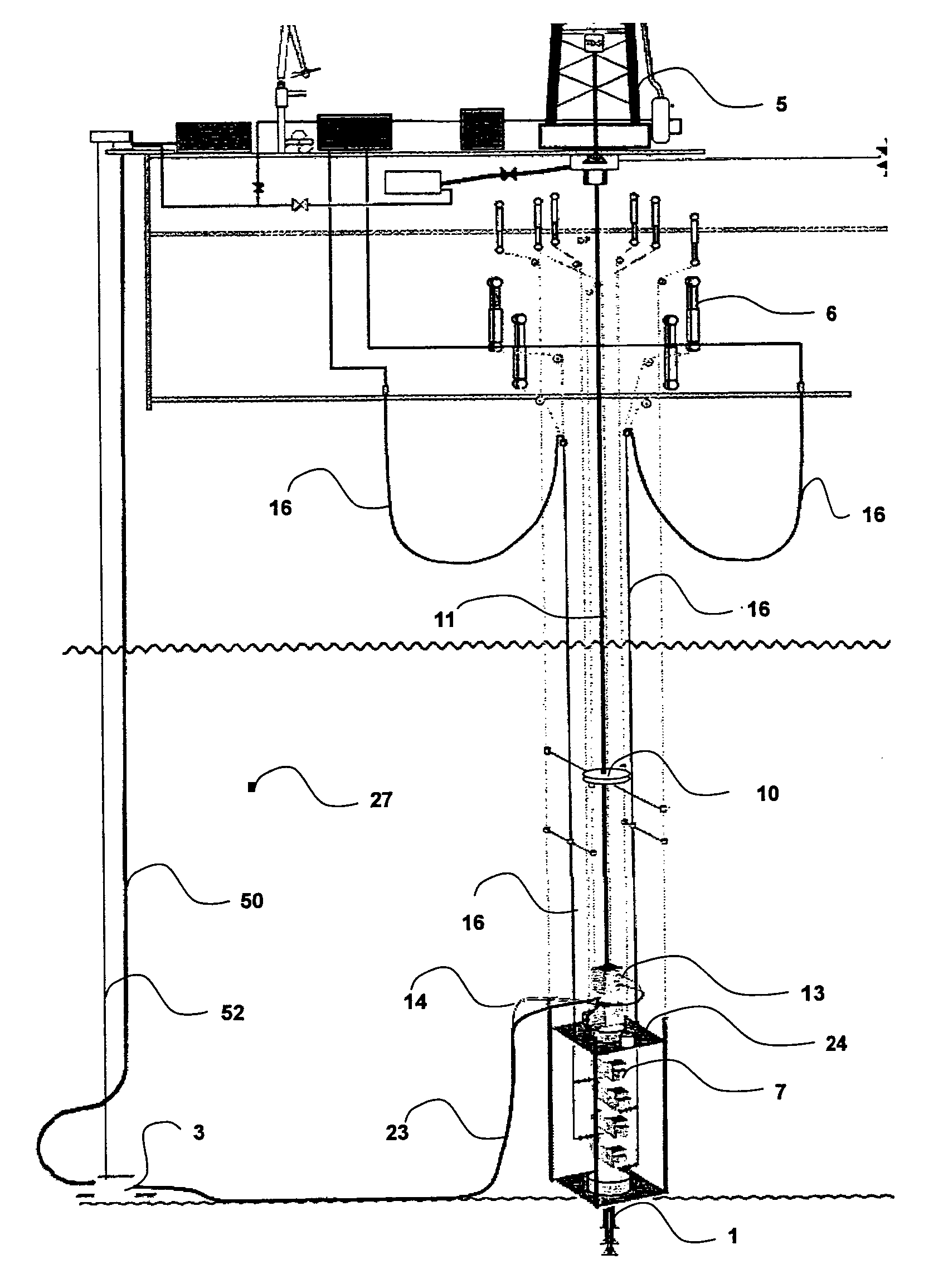
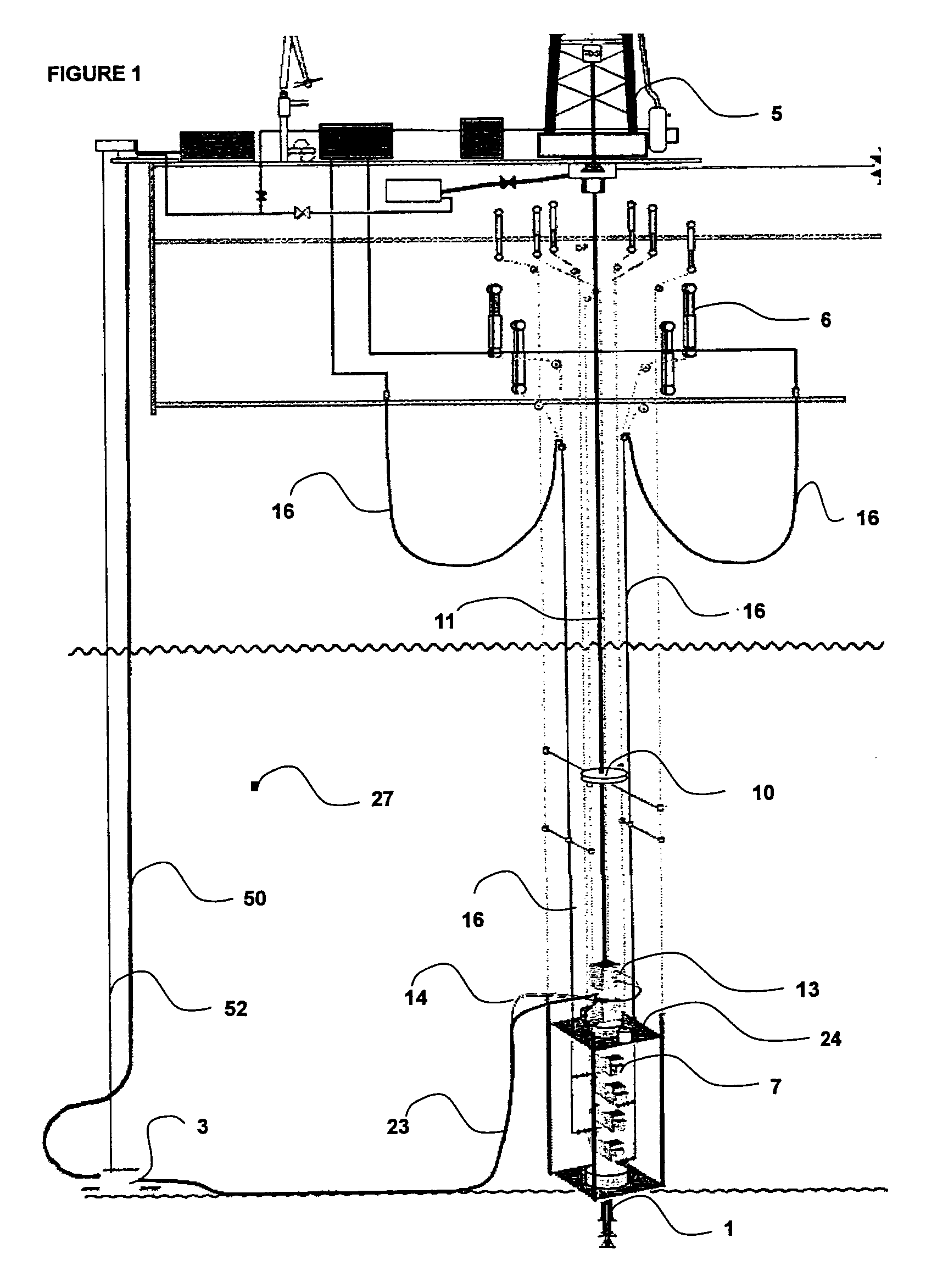
[0039]FIG. 1 (not to scale) shows a simplified schematic of the invention. A drilling unit MODU (5) is shown, with a drill string (11) deployed subsea and into the well being drilled in seawater (27). The drilling unit MODU (5) maintains its location over the well co-ordinates. On the subsea wellhead (1), a riserless blowout preventer stack (7) with a simplified LRMP on top is installed which provides secondary well control capability and renders physical connection to the subsea booster pump (3) package. The physical connection between the riserless blowout preventer stack (7) (LMRP) and the subsea booster pump (3) package is via flexible umbilicals.

[0040]The services required for the subsea booster pump (3) package and the riserless blowout preventer stack (7) are connected to the drilling unit MODU (5) by a vertical (possibly composite) hose bundle (52) connected between the seafloor or subsea free hanging installed subsea booster pump (3) module and the topsides MODU (5). The ve...

second embodiment

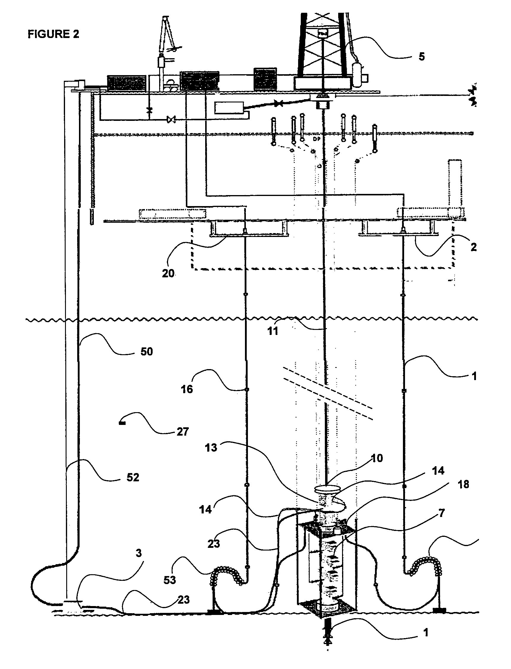
[0043]FIG. 2 (not to scale) shows a simplified schematic of the invention and uses the same sub components as the former arrangement described in FIG. 1, however in this case, the flexible choke and kill lines (16) are not top tensioned and instead, vertical displacements of the drilling unit MODU (5), under the influence of prevailing sea states, are accommodated by a ‘reverse pliant’ wave (53) formed by the over length flexible pipe in near proximity to the seafloor. The flexible choke and kill lines (16) are terminated on the lower marine riser package receiver plate (18) using gooseneck assemblies (54). The length of flexible choke and kill lines (16) can be built and pre-installed prior to the commencement of a drilling campaign and thereafter remain in-situ. The sections of flexible choke and kill line (16) will be assembled individually and the increasing built length hung on supplementary basement decks (20). Such a hang-off and storage amenity will be fully used whenever th...


PUM


Abstract

The invention provides a drilling system for drilling subsea wells from a floating mobile offshore drilling unit (MODU), the system comprising a subsea BOP. The system is distinctive in that the subsea BOP has relative small weight and size, the system includes no marine riser but the system comprises: flexible choke and kill lines arranged between the subsea BOP and the MODU, means for drill string guidance and cleaning, for guiding when inserting or taking out a drill string from the BOP and for drill string cleaning when pulling the drill string out from the BOP, means for controlled leakage of seawater into a recovery funnel arranged below the means for drill string cleaning but above the BOP, and means for return from the recovery funnel to the MODU of drilling fluid and seawater leaked into the recovery funnel.

Description

RELATED APPLICATIONS[0001]This application is a US National Phase Application filed under 35 USC 371 of PCT Application No. PCT / NO2011 / 000216, filed 29 Jul. 2011, which claims the benefit of Norwegian Application No. NO 20101087, filed 30 Jul. 2010. Each of these applications is herein incorporated by reference in their entirety for all purposes.FIELD OF THE INVENTION[0002]The present invention relates to drilling offshore for petroleum to reservoirs located subsea, whereby the drilling takes place from a floating mobile offshore drilling unit, a so called MODU. With the present invention several of the problems associated with such drilling activities are mitigated or eliminated, as will be explained below.BACKGROUND OF THE INVENTION AND PRIOR ART[0003]In offshore drilling, there is an increasing demand for prolonged service life of the well assembly or equipment and also there is a demand for reduced or eliminated pollution to sea from the drilling activities and reduced equipment...

Claims


Application Information

Patent Timeline
Patent Type & Authority Patents(United States)
IPC IPC(8): E21B7/12E21B33/08E21B21/08E21B21/00E21B7/128E21B33/064
CPCE21B7/12E21B7/128E21B21/001E21B21/08E21B33/064E21B33/085
Inventor POTTER, PAUL ANTHONYGLEDITSCH, SVEIN
Owner ENHANCED DRILLING
Why Eureka
Try Eureka