Lighting system

a lighting system and light technology, applied in the field of illumination devices, can solve the problems of inability to meet the requirements of indirect and direct lighting, the light system elastically bends due to its own weight, and the glare requirements and/or the conditions may not be met, so as to improve the mechanical stiffness of the lighting system, reduce the cost of manufacturing, and improve the effect of mechanical stiffness

Inactive Publication Date: 2011-03-03
KONINKLIJKE PHILIPS ELECTRONICS NV
View PDF10 Cites 7 Cited by
  • Summary
  • Abstract
  • Description
  • Claims
  • Application Information

AI Technical Summary

Benefits of technology

[0023]In a further embodiment of the lighting system according to the present invention, the light guiding plate may have two curvatures arranged to form the light guiding plate into a saddleback surface. In this manner, the mechanical stiffness of the lighting system is improved in two directions, i.e. in the directions of the axes about which the curvatures are curved. This is particularly useful when the overall size of the lighting system is substantially in the form of a square. Also, as a result of the different curvatures of the light emitting surface, different beam widths may be provided at different locations at the light emitting surface. Moreover, for some applications, a saddleback surface may provide an appealing design.
[0024]The light guiding plate may have a plurality of curvatures in yet other embodiments of the present invention. It is preferred that said plurality of curvatures has the same radius and is arranged to form the light guiding plate into a periodic shape, preferably a sinusoidal shape. Advantageously, the total height of the lighting system may be less than for a lighting system comprising a light guiding plate with only one curvature, under the condition that substantially each radius of the curvatures of the light guiding plate with a plurality of curvatures is equal to or approximately equal to the radius of the curvature of the light guiding plate with only one curvature and that the size of the lighting systems is equal. A further advantage is that a variety of products may be based on the same basic component, which in this case would be a flat light guide plate, comprising LEDs. By shaping the basic component different light distributions may be achieved. In this manner, cost of manufacturing may be less (high volumes of the basic component) and cost of logistics may be less (forming of the lighting system may be performed at a location different from the place of manufacturing and flat lighting system may require less space than curved lighting systems).

Problems solved by technology

However, when these lighting systems are suspended in, for example, an office environment or outside a building, the lighting system elastically bends due to its own weight.
For example, glare requirements and / or conditions for indirect and direct lighting may not be fulfilled.

Method used


Image

  • Lighting system
  • Lighting system
  • Lighting system

Examples


Embodiment Construction

[0032]Throughout the following description similar reference numerals have been used to denote similar elements, parts, items or features, when applicable.

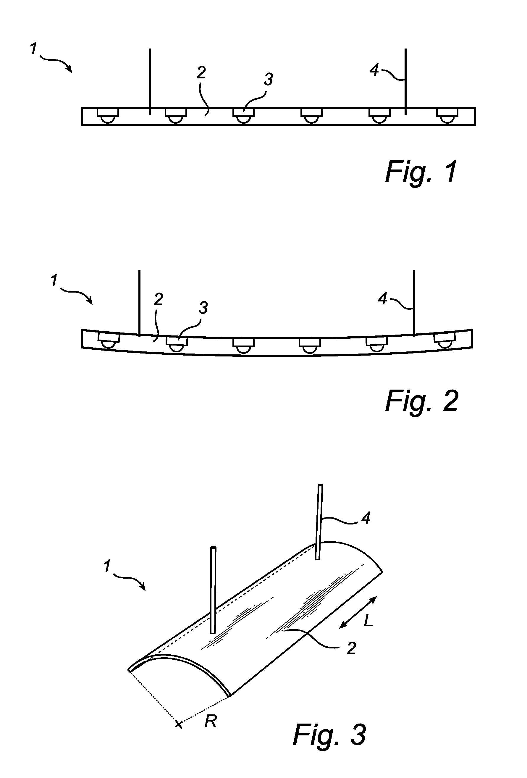
[0033]FIG. 1 shows a prior art lighting system as described above.

[0034]In FIG. 2, there is shown the prior art lighting system according to FIG. 1, when suspended, as described above.

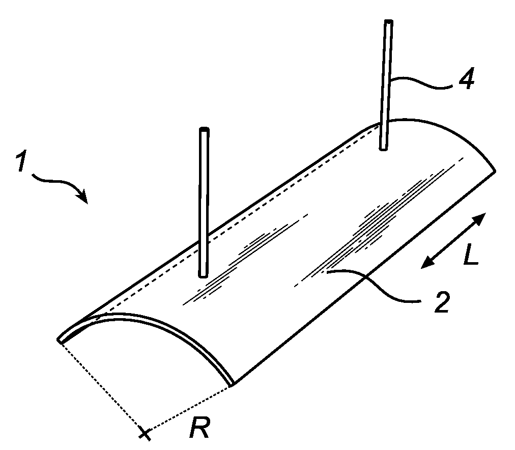
[0035]Referring to FIG. 3 there is demonstrated an exemplifying embodiment of the lighting system according to the present invention. The size of the lighting system is, typically, 100×20 cm and the thickness is approximately 5 mm. As a result, the light emitting surface is approximately 100×20 cm. The lighting system 1 comprises a light guiding plate 2, which encloses a plurality of LEDs 3. The LEDs are arranged to face in a direction along a normal to the light guiding plate.

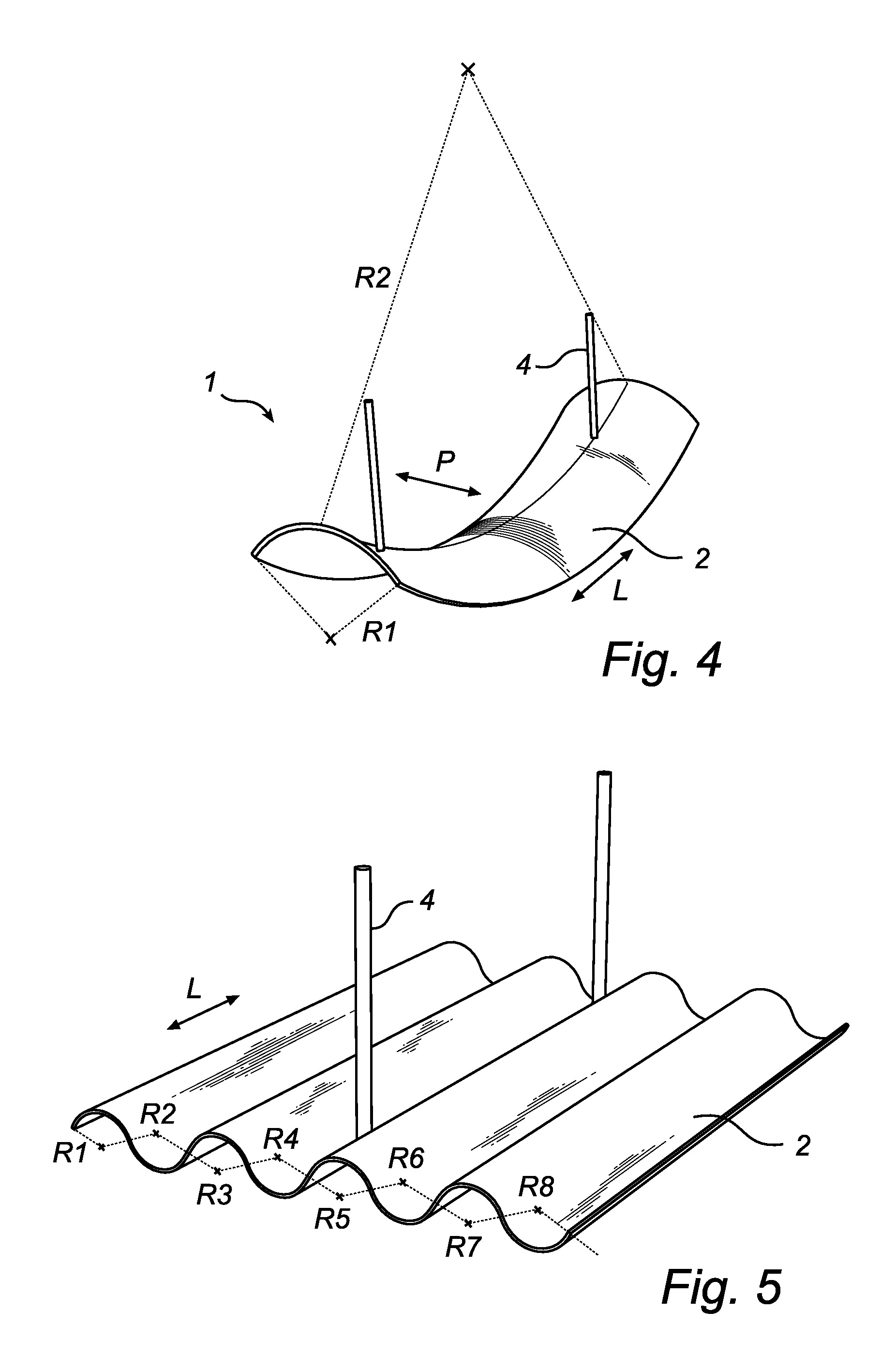
[0036]In a preferred, alternative example of the lighting system according to the present invention, the LEDs are arranged to face in a direction along a longitudinal axis of t...


PUM


Abstract

The present invention relates the field of illumination devices, in particular to a lighting system (1) comprising an elongated light guiding plate (2), comprising at least one light source (3). The light source (3) is enclosed in the light guiding plate (2). Furthermore, the light guiding plate (2) has at least one curvature (R).

Description

FIELD OF THE INVENTION[0001]The present invention relates the field of illumination devices, in particular to a lighting system comprising an elongated light guiding plate.BACKGROUND OF THE INVENTION[0002]In the field of lighting for interior and exterior use, there is an increasing need to integrate the lighting systems as unobtrusively as possible. This enables architects and interior designers to, by means of lighting, create a style that clearly distinguishes one building from another or one room from another. The commonly used fluorescent lamp fixtures usually have a thickness of about 5 cm. It is, however, expected that these fluorescent lamp fixtures will be replaced by thin, LED-based illumination systems within a near future. Many of these illumination systems, typically, have a thickness of less than 10 mm.[0003]In office environments, it is often desired to provide direct lighting for workspaces and indirect lighting for providing general lighting. Light fixtures with ind...

Claims


Application Information

Patent Timeline
Patent Type & Authority Applications(United States)
IPC IPC(8): F21V5/00F21V11/00
CPCG02B6/0073G02B6/0021F21S8/06
Inventor VERBRUGH, STEFAN MARCUSJALINK, CORNELIS JOJAKIM
Owner KONINKLIJKE PHILIPS ELECTRONICS NV
Why Eureka
Try Eureka