Optical head device

a head device and optical head technology, applied in the field of optical head devices, can solve the problems of increasing the operation speed of the actuator, reducing the mechanical stiffness of the head device, and reducing so as to improve the mechanical stiffness, and reduce the size/thickness of the optical head device

Inactive Publication Date: 2005-10-27
KK TOSHIBA
View PDF2 Cites 2 Cited by
  • Summary
  • Abstract
  • Description
  • Claims
  • Application Information

AI Technical Summary

Benefits of technology

[0010] The present invention is made in consideration of the circumstances described above, and an object thereof is to provide an optical head device which enables simultaneous pursuit of reducing size / thickness and increasing mechanical stiffness of the optical head device, in the optical head device as an optical system component of an optical disc device which reads or writes information from / to an optical disc.
[0012] More specifically, the optical base has a space for containing the actuator and the mirror, and on the back of the reflection plane of the mirror there exists the rear surface substantially parallel to the reflection plan. Consequently, a cross-sectional shape of the mirror is not a right triangle but is recessed on the rear surface side compared to the right triangle. Since the recess provides a new space, a beam is built newly in the new space, functioning as a part of the optical base. As a result, the space for containing the actuator and the mirror is divided by this beam, becoming small as an opening, and stiffness of the optical base is improved. Accordingly, simultaneous pursuit of reducing size / thickness of the optical head device and increasing mechanical stiffness as the optical head device can be achieved.
[0013] According to the present invention, in the optical head device as the optical system component of the optical disc device which reads or writes from / to the optical disc, simultaneous pursuit of reducing size / thickness of the optical head device and increasing mechanical stiffness as the optical head device can be achieved.

Problems solved by technology

Such a deformation becomes an obstacle for the optical system to soundly exert its function.
In particular, when faster writing (for example, 24 times speed for a CD, 8 times speed for a DVD) comes to be required of the optical disc device, an operation speed of the actuator becomes faster, relatively increasing a side effect as being an unnecessary vibratory source.
In this example, the actuator is mounted on the optical base without an inside frame area and ultimate reduction of thickness is not achieved.

Method used


Image

  • Optical head device
  • Optical head device
  • Optical head device

Examples


Embodiment Construction

Description of Embodiments

[0017] Embodiments of the present invention will be described with reference to the drawings, but these drawings are presented only for the illustrative purpose and in no respect, are intended to limit the present invention.

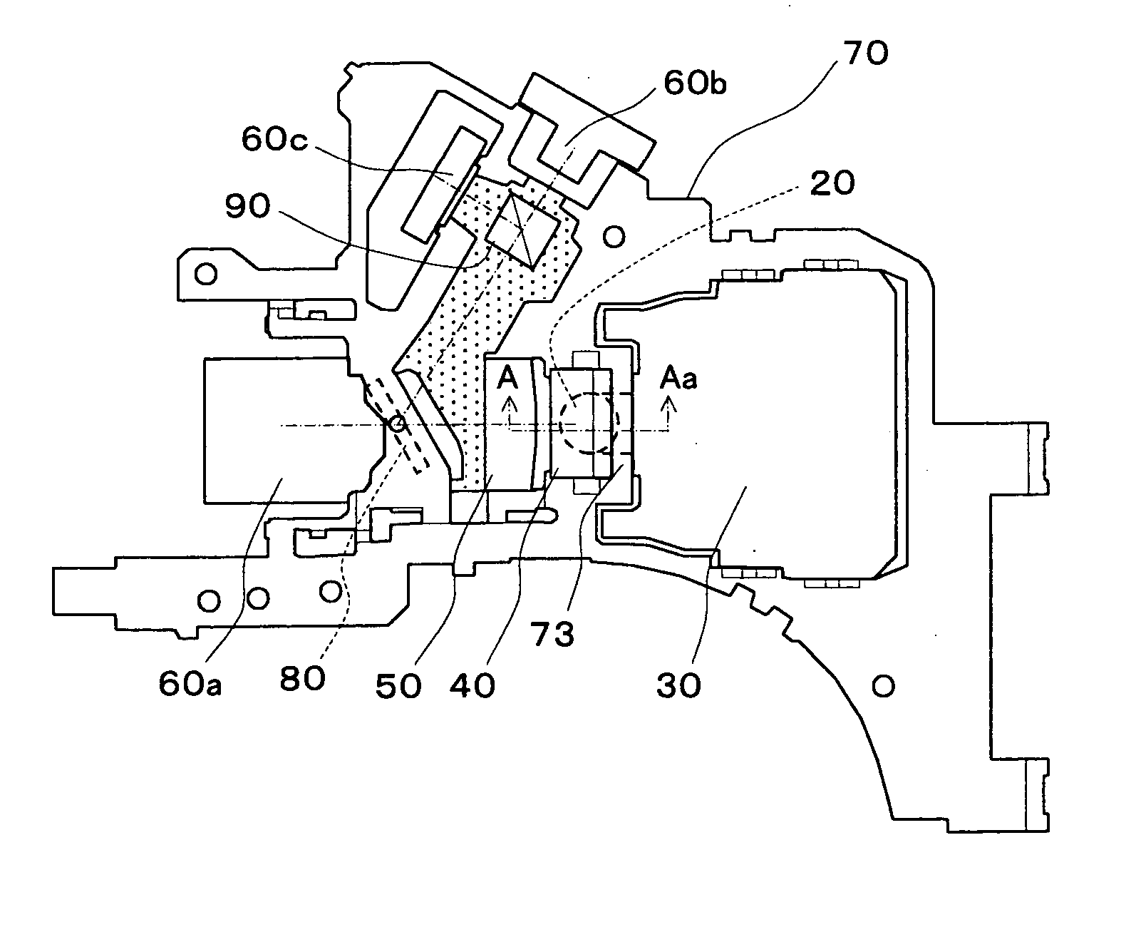
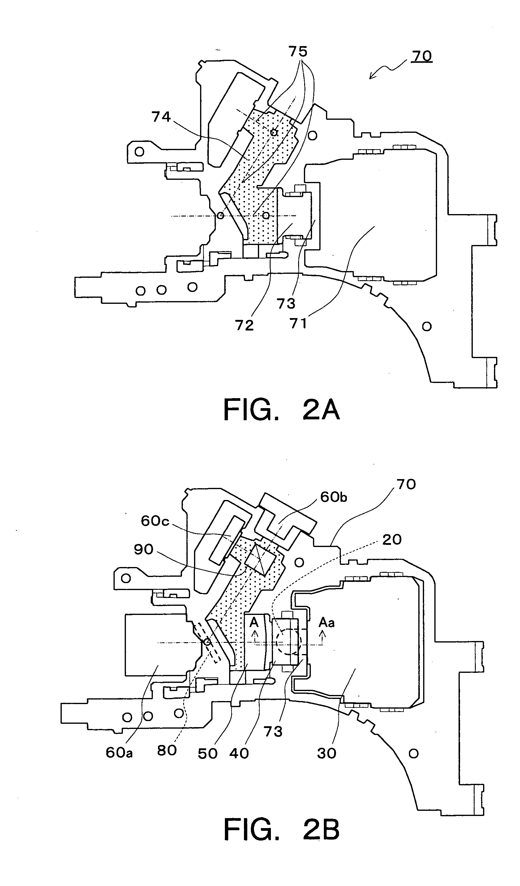
[0018] As an aspect of the present invention, a cross-sectional shape of the beam of the optical base can be a right triangle having a hypotenuse substantially parallel to the rear surface of the mirror. The beam having a shape which simply follows the cross-sectional shape of the mirror is built.

[0019] As another aspect, the cross-sectional shape of the beam of the optical base can be a shape which is included in the right triangle having the hypotenuse substantially parallel to the rear surface of the mirror and at the same time a shape which has a recessed portion on a side of the hypotenuse of the right triangle. For the cross-sectional shape of the beam, a triangular shape having a hypotenuse substantially parallel to the rear su...


PUM

PropertyMeasurementUnit
of wavelengthaaaaaaaaaa
wavelengthaaaaaaaaaa

Abstract

Disclosed is an optical head device including: an object lens; an actuator displacing the optical lens; a mirror which has a reflection plane to bend a direction of a light traveling on an optical axis of the object lens, and on a back of the reflection plane, a rear surface substantially parallel to the refection plane; and an optical base which has openings for incorporating the actuator and the mirror and which has a beam at a position opposed to the rear surface of the mirror.

Description

CROSS-REFERENCE TO RELATED APPLICATION [0001] This application is based upon and claims the benefit of priority from the prior Japanese Patent Application No. 2004-131676, filed on Apr. 27, 2004; the entire contents of which are incorporated herein by reference. BACKGROUND [0002] 1. Field of the Invention [0003] The present invention relates to an optical head device as an optical system component of an optical disc apparatus which reads or writes information from / to an optical disc, more particularly, to a preferred optical head device suitable for reducing size (thickness) of the optical disc device. [0004] 2. Description of the Related Art [0005] In a field of the optical disc apparatus, that of a thinner structure is desired as a drive to be embedded in a compact personal computer such as a laptop personal computer. Consequently, as the optical head device to be embedded in the laptop personal computer, the structure of the optical head device is virtually limited to the one con...

Claims


Application Information

Patent Timeline
Patent Type & Authority Applications(United States)
IPC IPC(8): G11B7/12G11B7/00G11B7/125G11B7/135G11B7/1362G11B7/22
CPCG11B7/1362G11B2007/0006G11B7/22
Inventor SHINOZUKA, HIROSHI
Owner KK TOSHIBA
Why Eureka
Try Eureka