Sample Stage

a technology of sample stage and sample, which is applied in the direction of basic electric elements, electrical equipment, electric discharge tubes, etc., can solve the problems of unfavorable sample movement, and achieve the effects of less noise, better contrast, and sharp images

Inactive Publication Date: 2017-11-02
PHENOM WORLD HLDG BV
View PDF19 Cites 2 Cited by
  • Summary
  • Abstract
  • Description
  • Claims
  • Application Information

AI Technical Summary

Benefits of technology

[0005]When positioning a sample accuracy of the position and stability of maintaining the position is of great importance. It is often undesirable that the sample moves, e.g. vibrates within the field of view during observation of the sample. Thereto, the ability of the sample stage to maintain the position of a sample, positioned on a sample carrier of the sample stage, is of great importance. One important aspect herein is the mechanical stiffness of the sample stage from the sample carrier to the base. It is known that displacement mechanisms, e.g. guide rails (e.g. for positioning the sample carrier in X, Y and / or Z directions), or rotation mechanisms (e.g. for rotating the sample carrier in R, T1 and / or T2 directions), can reduce the overall mechanical stiffness of the sample stage. In the past much effort has been put into designing displacement mechanisms and rotation mechanisms with high mechanical stiffness.
[0028]In order to enhance the user experience, and to increase reaction speed of the system when displaying live images during changes to a region of interest, the inventors realized that it is beneficial that the processor includes a second input for receiving process information representative of changes to a condition of the microscope, and that the processor is further arranged for automatically, in response to receiving on the second input an indication of a change to the condition of the microscope, switch to outputting to the output a live image of a second type based on a second number of recent images received at the first input, the second number being smaller than the first number. Since the live image of the second type is based on a smaller number of recent images received at the first input effects of the change to the condition of the microscope, such as motion artefacts, to the live image of the second type will be smaller than to the live image of the first type. Conversely, since the live image of the second type is based on a smaller number of recent images received at the first input image improvement of the live image of the second type will be smaller than image improvement of the live image of the first type.

Problems solved by technology

It is often undesirable that the sample moves, e.g. vibrates within the field of view during observation of the sample.

Method used


Image

  • Sample Stage
  • Sample Stage
  • Sample Stage

Examples


Embodiment Construction

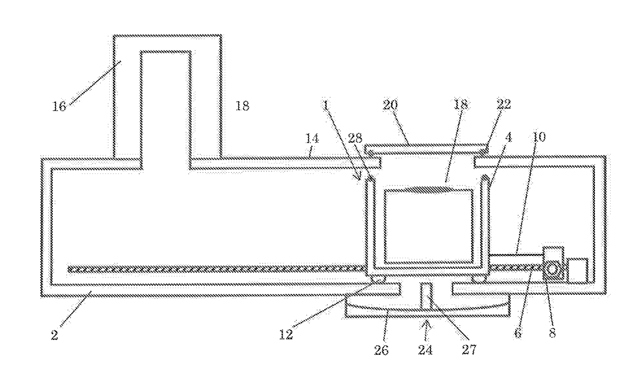
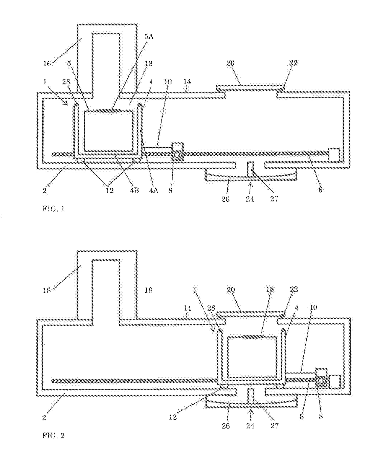
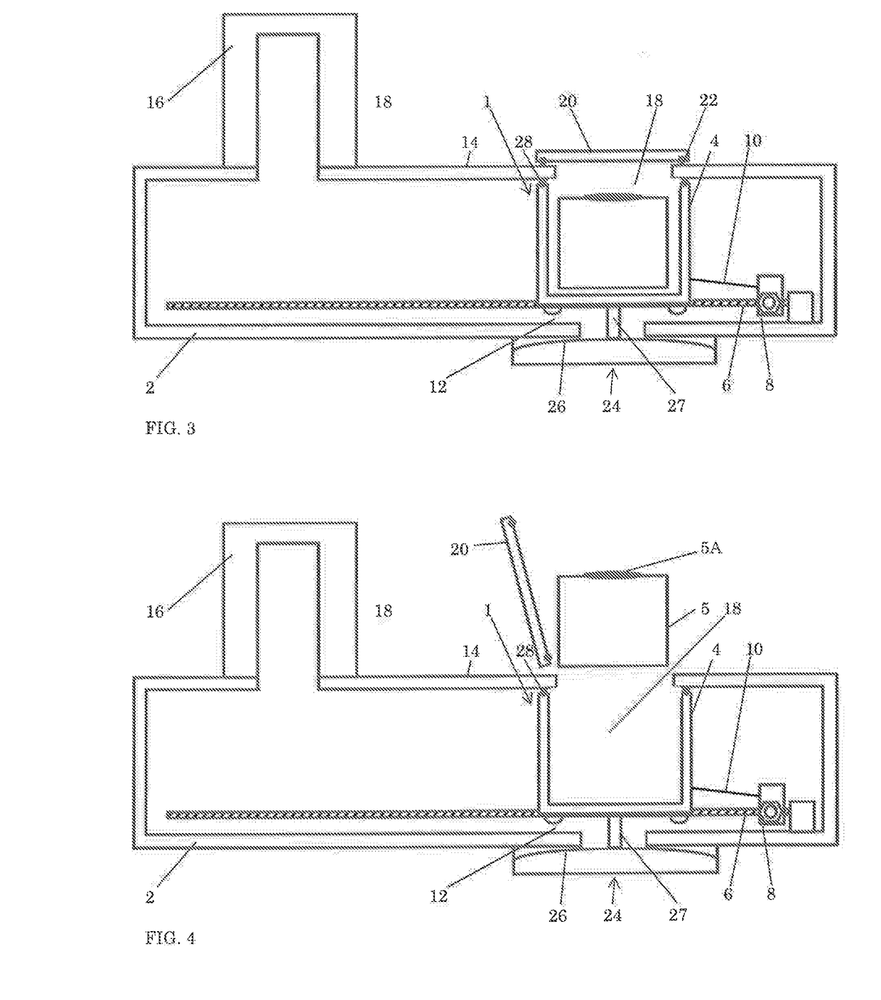
[0042]FIG. 1 shows a schematic representation of a system having aspects according to the invention. FIG. 1 shows, by way of non-limiting example a schematic representation of a scanning electron microscope. FIG. 1 shows a sample stage 1 positioned inside a vacuum chamber 14. The sample stage 1 includes a sample carrier 4. In this example the sample carrier 4 includes a bottom 4A and a circumferential wall 4B enclosing a cavity 18 for holding a sample or a sample holder. In this example the cavity 18 holds an exchangeable sample holder 5. The exchangeable sample holder 5 holds a sample 5A.

[0043]The sample stage 1 further includes a base 2. The sample carrier 4 is positioned on the base 2. In FIG. 1 the sample carrier 4 includes sliding feet 12 for allowing sample carrier 4 to slidingly move along the surface of the base 2. Since the sample carrier 4 directly abuts against the base 2, and here is pressed against the base by gravity, the mechanical stiffness of the sample stage 1 from...


PUM


Abstract

Sample stage, e.g. for use in a scanning electron microscope. The sample stage includes a base, a sample carrier, and an actuator assembly arranged for moving the sample carrier in at least one direction substantially parallel to the base. The actuator assembly is arranged so as not to contribute to the mechanical stiffness of the sample stage from the sample carrier to the base.

Description

FIELD OF THE INVENTION[0001]The present invention concerns a sample stage. More specifically the invention relates to a sample stage for use in an electron microscope. The invention also relates to a vacuum system, such as for use in an electron microscope. The invention also relates to an improved load lock.BACKGROUND TO THE INVENTION[0002]Sample stages are commonly used for moving a sample relative to a reference position. The reference position can e.g. be related to a field of view of a microscope such as a scanning electron microscope. The reference position can e.g. be an optical axis or a beam position. The sample stage allows positioning and repositioning of the sample relative to the reference position, e.g. to allow inspection of certain features of the sample, or to allow inspection of a surface area larger than the field of view.[0003]A load lock forms a port between the inside atmosphere of an apparatus, such as an electron microscope, and the outside atmosphere. Load l...

Claims


Application Information

Patent Timeline
Patent Type & Authority Applications(United States)
IPC IPC(8): H01J37/20H01J37/18H01J37/28
CPCH01J37/20H01J37/18H01J2237/20235H01J2237/2006H01J2237/20228H01J37/28H01J37/185H01J2237/20221H01J2237/204H01J2237/28H01J2237/0216H01J2237/184H01J37/261
Inventor STAMSNIJDER, GERHARDUS BERNARDUSVAN DEN BOS, PAUL CORNELIS MARIAKLUIJTMANS, TON ANTONIUS CORNELIS HENRICUSSTOKS, SANDER RICHARD MARIEHAMMEN, ADRIANUS FRANCISCUS JOHANNESVAN DER MAST, KAREL DIEDERICK
Owner PHENOM WORLD HLDG BV
Why Eureka
Try Eureka