Industrial robot including a parallel kinematic manipulator

a technology of kinematic manipulators and industrial robots, applied in the direction of manipulators, joints, weapons, etc., can solve the problems of inability to achieve the features of scara manipulators, need a lot of vertical space, and the prior art robots will also be heavy, so as to achieve less variations of robot stiffness

Active Publication Date: 2019-01-01
ABB (SCHWEIZ) AG
View PDF10 Cites 2 Cited by
  • Summary
  • Abstract
  • Description
  • Claims
  • Application Information

AI Technical Summary

Benefits of technology

[0007]One object of the present invention is to provide a parallel kinematic robot, which is compact, less expensive than the disclosed Scara Tau manipulator, and has a large work space compared to the space it occupies, i.e. has a small footprint.
[0010]With the term “the support member is arranged to rigidly support at least one of the actuators” is meant that the support member is arranged to support the actuator in such a way that the mechanical stiffness of the mounting of the two components relative each other is high, which means that the stiffness of the support member and the mounting interfaces between the support member and the actuators are designed to be stiff. The support member may be arranged to support the actuator alone or as a part of a support structure supporting the actuator. It should be noticed that the support member can either be a specific mechanical member or be part of the encapsulation of the actuator. For example, the support member is mechanically rigidly connected to at least one of the first and second actuators, which means that the support structure and the actuator are mounted either in direct contact with each other or via one or more other components in such a way that the mechanical stiffness of the mounting of the two components relative each other is high.
[0011]The invention provides a possibility to make installations with a high manipulator density and is favorable when the robot is working from the side of, for example, a conveyor. This mounting also makes it easy to install and exchange the robot and the robot will be easily accessible for service and maintenance. Since it is possible to move the robot arms and platform outside the work space, cleaning and washing of the robot will be easier since it is not necessary to do this above, for example, a conveyor.
[0014]According to an embodiment of the invention, the transmission unit comprises a gear ring connected by at least one pinion gear to the drive shaft of the third actuator. This is a simple way to obtain a high gear ratio because of the relatively large diameter of the gear ring.
[0015]According to an embodiment of the invention, the third actuator is mechanically connected to the support member. This will give a compact design for the actuator, which will not need to output as much torque as the other actuators because of the gear ratio possible to obtain with the large diameter ring gear.
[0019]According to an embodiment of the invention, one of the arms has an outer arm part including three links pivotally connected to the respective inner arm part and to the platform. This will make it possible to obtain less variations of the stiffness of the robot.

Problems solved by technology

However, the Scara manipulator has some features that cannot be achieved by the Delta manipulator, as for example small footprint, possibility to mount the manipulator beside the work space, possibilities to obtain a larger vertical stroke and the possibilities to make installations with a higher manipulator density.
This means that even if the robot obtains a small footprint it will need a lot of space in the vertical direction.
This is especially a problem if the robot is used to serve for example a conveyor, especially if the robot must be mounted over the conveyor.
Beside the need of a large space in the z-direction, the prior art robot will also be heavy because of the mounting column supporting the arms and the actuation system.

Method used


Image

  • Industrial robot including a parallel kinematic manipulator
  • Industrial robot including a parallel kinematic manipulator
  • Industrial robot including a parallel kinematic manipulator

Examples


second embodiment

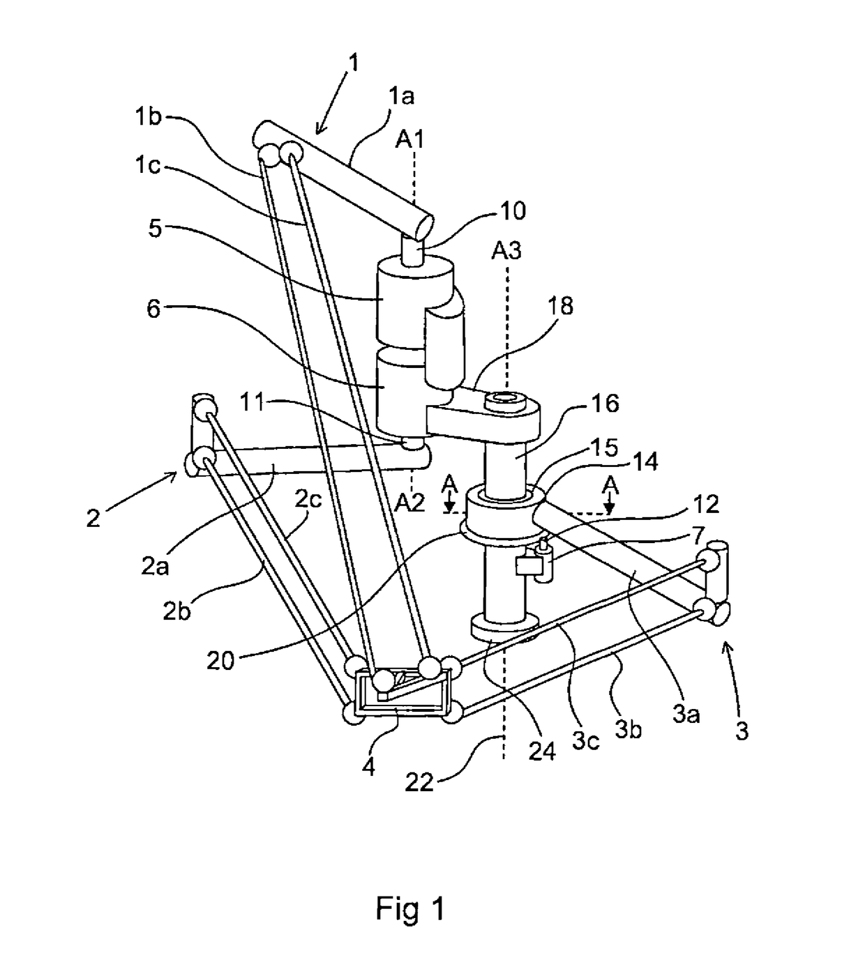
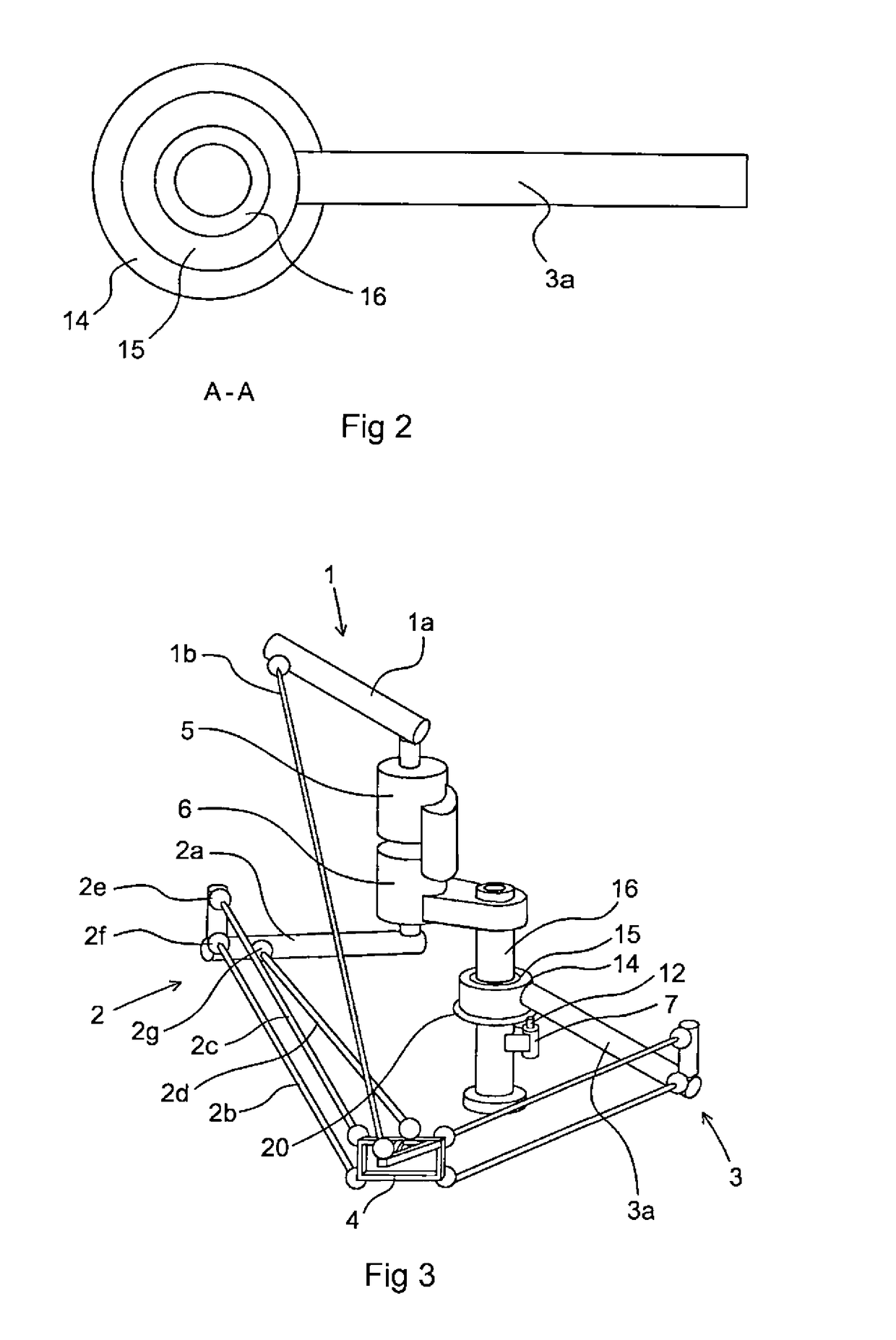
[0037]FIG. 3 shows a manipulator according to the invention. This manipulator differs from the manipulator shown in FIG. 1 in that the first outer arm part includes only one link 1b pivotally connected by joints to the first inner arm part 1a and to the platform 4, and in that the second outer arm part includes three links 2b-d pivotally connected to the second inner arm part 2a and to the platform 4. The yaw angle of the platform 4 is here constrained by the link 2d. In FIG. 1 it is the pair of links 1b and 1c that constrains the yaw angle. Also here the platform rotations when the platform moves in a radial direction can be reduced by mounting the joint 2g close to a line between the joints 2e-f connecting the links 2b-c with the second inner arm part 2a. Seen both from above and from the side, the link 2d is not parallel with the parallel links 2b-c. This will reduce the yaw variations of the platform when it is moved in the work space.

third embodiment

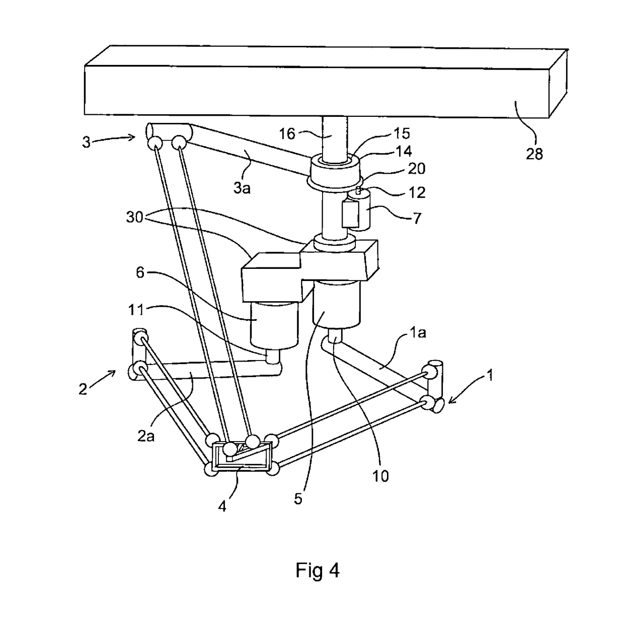
[0038]FIG. 4 shows a manipulator according to the invention. The manipulator shown in FIG. 4 differs from the manipulator shown in FIG. 1 in that the third arm 3 is arranged for influencing the platform 4 in mainly a vertical direction, and the first arm 1 is arranged for influencing the platform 4 in a mainly horizontal direction. Further, the first and second actuators 5, 6 are arranged displaced in a horizontal direction. The support member 16 is connected to a roof beam 28. The first and second actuators 5, 6 are rigidly connected to the support member 16 via supporting elements 30. The third actuator 7 is rigidly connected to the support member 16. The third inner arm part 3a is mounted on the hollow part 14 driven by the third actuator 7 having a drive shaft 12 engaging the gear teeth of the gear ring 20 in the same way as in FIG. 1. In this way the same robot structure mounted on the floor as in FIGS. 1 and 3 can also be mounted in the roof above the work space, which is nece...

fourth embodiment

[0039]FIG. 5 shows a manipulator according to the invention. It can be used to increase the work space when the actuators are mounted directly on a vertical application dependent support structure. The support structure of the embodiment shown in FIG. 5 comprises a vertically arranged support beam 40, a first holding device 42 on which the second actuator 6 is mounted, a second holding device 44 on which the first actuator 5 is mounted, and a distance piece 45 arranged to displace the third inner arm part 3a from the second inner arm part 2a in the direction of the shaft 12. The third actuator 7 is rigidly connected to the distance piece 45. The support structure further comprises a support member 48 arranged to rigidly support the first actuator 5. One end of the support member 48 is attached to the first holding device 42 and the other end is attached to the second holding device 44. The first actuator 5 is rigidly connected to the support member 48 via the second holding device 4...


PUM


Abstract

An industrial robot including a manipulator for movement of an object in space. The manipulator includes a movable platform arranged for carrying the object, a first arm arranged for influencing the platform in a first direction and including a first inner arm part rotatable about a first axis, a second arm arranged for influencing the platform in a second direction and including a second inner arm part rotatable about a second axis, a third arm arranged for influencing the platform in a third direction and including a third inner arm part rotatable about a third axis.

Description

FIELD OF THE INVENTION[0001]The present invention relates to an industrial robot including a manipulator for movement of an object in space, where the manipulator is a parallel kinematic manipulator.[0002]A parallel kinematic manipulator includes a movable platform arranged for carrying the object, a first arm arranged for influencing the platform in a first direction and including a first inner arm part, a first outer arm part pivotally connected to the first inner arm part and to the platform, and a first actuator having a first drive shaft for actuating the first arm, a second arm arranged for influencing the platform in a second direction and including a second inner arm part, a second outer arm part pivotally connected to the second inner arm part and to the platform, and a second actuator having a second drive shaft for actuating the second arm, a third arm arranged for influencing the platform in a third direction and including a third inner arm part, a third outer arm part p...

Claims


Application Information

Patent Timeline
Patent Type & Authority Patents(United States)
IPC IPC(8): B25J17/02
CPCB25J17/0266B25J17/02
Inventor BROGARDH, TORGNYISAKSSON, MATS
Owner ABB (SCHWEIZ) AG
Why Eureka
Try Eureka