Feeding device and image forming apparatus
a technology of feeding device and image forming apparatus, which is applied in the direction of thin material processing, article separation, transportation and packaging, etc., can solve the problems of shortening the time required to convey a sheet, image defects, etc., and achieves good images and shortening the fpot
- Summary
- Abstract
- Description
- Claims
- Application Information
AI Technical Summary
Benefits of technology
Problems solved by technology
Method used
Image
Examples
first embodiment
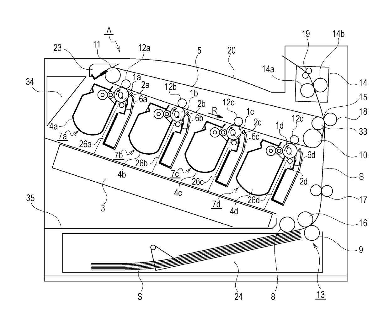
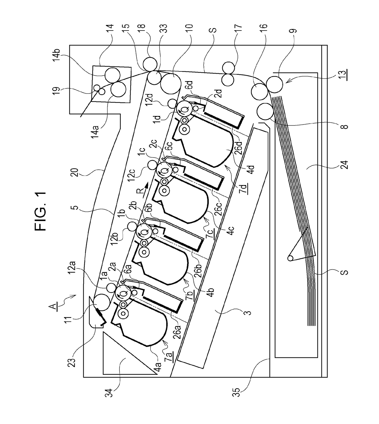
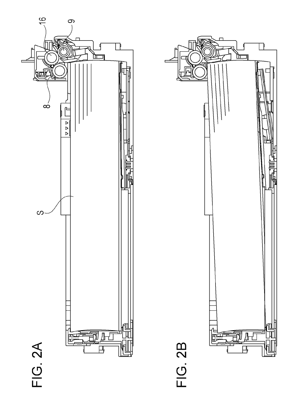
[0032]An image forming apparatus according to a first embodiment will be described with reference to FIGS. 1 to 15A and 15B. In the following description, the overall configuration of the image forming apparatus will be first described with reference to FIG. 1. Next, the structure of a sheet feeding device will be described with reference to FIGS. 2A and 2B to 13A and 13B.
[0033]First, the overall configuration of the image forming apparatus will be described with reference to FIG. 1. An image forming apparatus A includes four process cartridges 7 (7a to 7d) juxtaposed while being inclined with respect to the horizontal direction. The process cartridges 7 (7a to 7d) include their respective electrophotographic photosensitive drums 1 (1a to 1d), each of which serves as one image bearing member.
[0034]The electrophotographic photosensitive drums (hereinafter referred to as “photosensitive drums”) 1 are rotated by a driving member (not illustrated) in the clockwise direction (direction o...
second embodiment
[0088]Next, a second embodiment will be described. In the following description of the second embodiment, descriptions of structures and operations common to the first embodiment are skipped appropriately. A feeding device according to the second embodiment is different from the first embodiment in the structure of a moving unit that moves a pickup roller 8 between a contact position (contact operation) and a retracted position (separating operation).
[0089]FIGS. 16A to 16C, 17A to 17C, and 18A to 18C are perspective views illustrating the structure of the moving unit in the feeding device of the second embodiment. FIGS. 16A, 17A, and 18A are perspective views of related components, as viewed from the rear side of a product, and FIGS. 16B, 17B, and 18B are perspective views of the related components, as viewed from the front side of the product. FIGS. 16C, 17C, and 18C are enlarged views of a gear engagement portion and a cam portion.
[0090]A gear holder 64 is held in a driving frame ...
PUM
 Abstract
Description
Claims
Application Information
 - R&D
- Intellectual Property
- Life Sciences
- Materials
- Tech Scout
- Unparalleled Data Quality
- Higher Quality Content
- 60% Fewer Hallucinations
Browse by: Latest US Patents, China's latest patents, Technical Efficacy Thesaurus, Application Domain, Technology Topic, Popular Technical Reports.
© 2025 PatSnap. All rights reserved.Legal|Privacy policy|Modern Slavery Act Transparency Statement|Sitemap|About US| Contact US: help@patsnap.com


