
Adjustable securing mechanism

a securing mechanism and adjustable technology, applied in the direction of loudspeakers, earpiece/earphone manufacture/assembly, non-occlusive ear tips, etc., can solve the problems of significant drawbacks and disadvantages, the majority of the devices employing the conventional securing means are easily dislodged, and the most conventional securing means do not self-adjust or self-conform to the shape of the internal spa

Active Publication Date: 2018-10-09
EARGO
View PDF81 Cites 5 Cited by
  • Summary
  • Abstract
  • Description
  • Claims
  • Application Information

AI Technical Summary

Benefits of technology

The mechanism provides extended wear comfort, secure engagement, and improved sound quality by reducing leakage and enhancing the fitting range of hearing aids, allowing for fluid flow and effective sound modulation.

Problems solved by technology

There are, however, a number of significant drawbacks and disadvantages associated with conventional securing means; particularly when employed on audio transmitting (or receiving) devices, such as an in-ear hearing device.
A major disadvantage of conventional securing means is that the securing means, e.g., securing rings and compliant outer surfaces, do not include any means for fluid flow through the device or between the securing means of device and the opening when the device is inserted therein.
Another drawback is that most of the devices employing the conventional securing means are easily dislodged.
A further drawback is that most conventional securing means do not self-adjust or self-conform to the shape of the internal space or opening when the space access device is inserted therein.
An additional drawback is that most of the conventional securing means do not include any means for modulating the amplitude and / or frequency of audio signal transmitted through the securing means and / or space access device associated therewith and / or the space between the surface of an internal space or opening and the space access device, when the space access device is inserted therein.
However, the smaller the ear canal is, the greater are the forces that are applied by the flanges to the ear canal surfaces, which can lead to discomfort to the user in shorter periods of time than may be desirable.
Also, since the body of the hearing aid conforms to the surfaces of the ear canal, it does not allow any air flow around any part of the hearing aid, as the hearing aid seals all along the walls of the ear canal.
Because the flanges are the sole source of anchoring, the forces applied by both sealing off and anchoring may be at a level that may become uncomfortable to the wearer in a shorter period of time then desired.

Method used


Image

  • Adjustable securing mechanism
  • Adjustable securing mechanism
  • Adjustable securing mechanism

Examples


Embodiment Construction

[0074]Before the present systems, devices, mechanisms and methods are described, it is to be understood that this invention is not limited to particular embodiments described, as such may, of course, vary. It is also to be understood that the terminology used herein is for the purpose of describing particular embodiments only, and is not intended to be limiting, since the scope of the present invention will be limited only by the appended claims.

[0075]It is also to be understood that, although the securing mechanism structures and systems of the invention are illustrated and described in connection with in-ear hearing devices, the securing mechanism structures and systems of the invention are not limited to in-ear hearing devices and systems. According to the invention, the securing mechanism structures and systems of the invention can be employed on any anatomical, i.e. biological, space access device or system, e.g. an in-ear head set, and non-biological space access device or sys...


PUM


Abstract

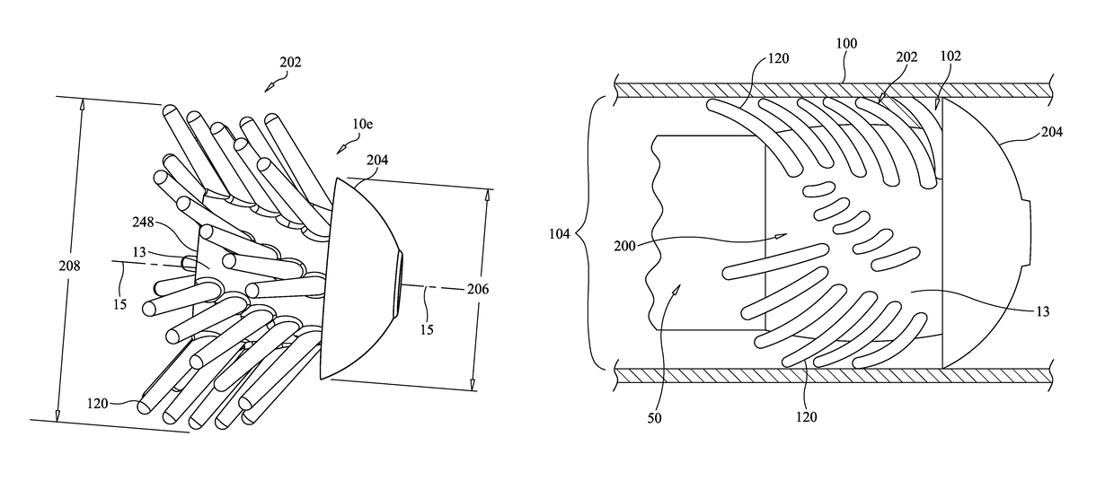
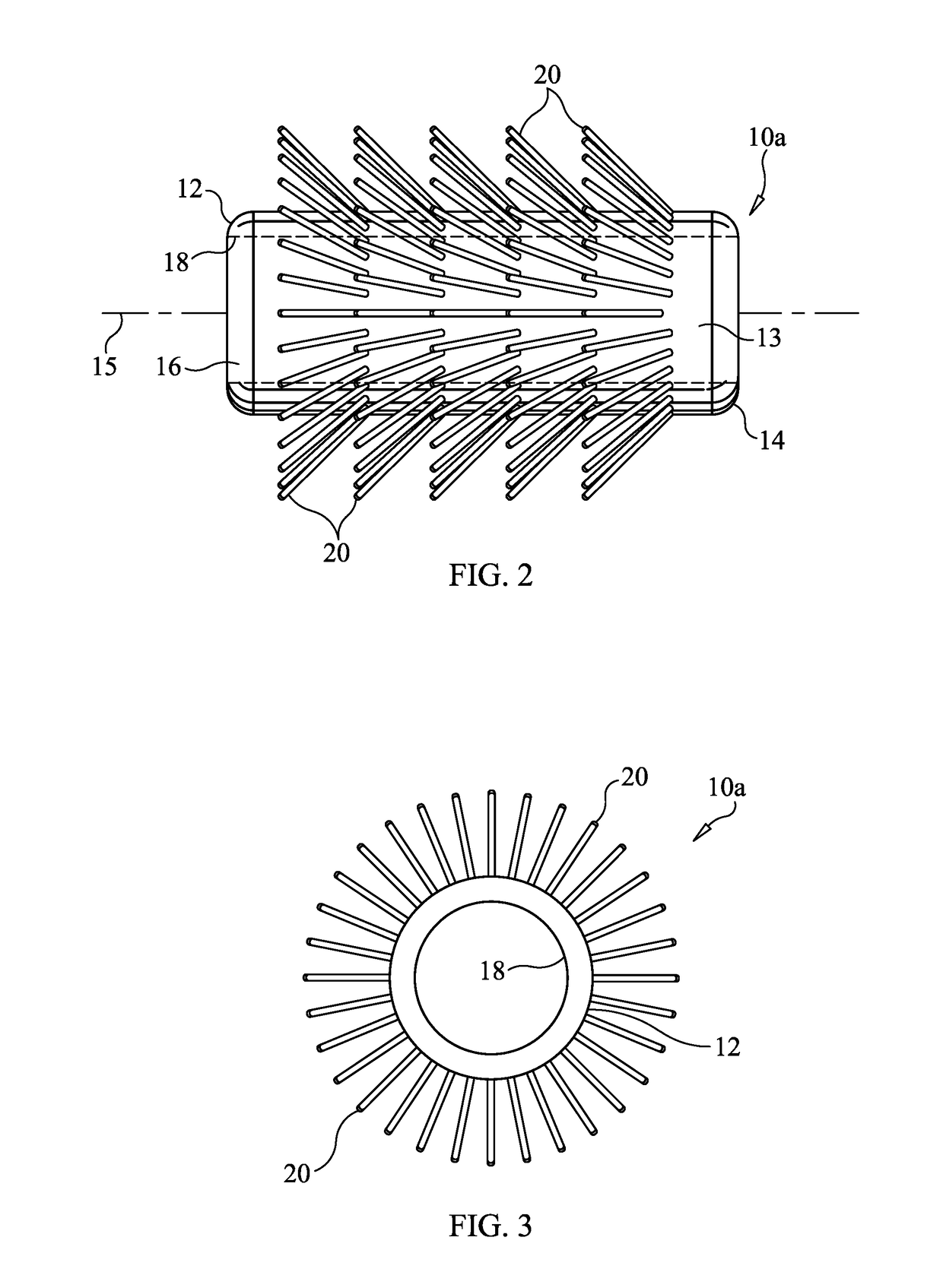
Securing mechanisms for space access devices, such as an audio signal transmitting device, include a plurality of outwardly projecting members that are configured to transition from a relaxed state to a securing state when the space access device is inserted into an internal space or opening that has an inside diameter smaller than an outside diameter of the outwardly projecting members in the relaxed state. The outwardly projecting members securely engage a surface of the internal space and conform to the shape and size of the internal space. A sound blocking portion can be provided to substantially prevent air / sound flow past the sound blocking portion of the securing mechanism.

Description

CROSS-REFERENCE[0001]This application is a continuation-in-part application of co-pending U.S. application Ser. No. 15 / 373,379, filed Dec. 8, 2016, which is a continuation-in-part application of co-pending U.S. application Ser. No. 15 / 195,100, filed Jun. 28, 2016, which is a continuation of U.S. application Ser. No. 14 / 032,310, filed Sep. 20, 2013, which is a continuation of U.S. application Ser. No. 13 / 865,717, filed Apr. 18, 2013, now U.S. Pat. No. 8,577,067, which is a continuation of U.S. application Ser. No. 12 / 841,120, filed Jul. 21, 2010, now U.S. Pat. No. 8,457,337, which claims the benefit of U.S. Provisional Application No. 61 / 228,571, filed Jul. 27, 2009 and claims the benefit of U.S. Provisional Application No. 61 / 228,588, filed Jul. 26, 2009, each of which applications and patents now being incorporated herein, in its entirety, by reference thereto and to which non-provisional applications we claim priority under 35 USC § 120 and to which provisional applications we cla...

Claims


Application Information

Patent Timeline
Patent Type & Authority Patents(United States)
IPC IPC(8): H04R25/00H04R25/02H04R1/42
CPCH04R25/656H04R25/02H04R25/456H04R25/48H04R25/606H04R25/652H04R2460/17H04R25/604H04R25/658H04R2225/023H04R2460/09H04R2460/11H04R2460/13H04R1/42H04R1/1016H04R1/105H04R1/1058H04R25/554H04R2201/103H04R2225/025H04R2420/07
Inventor BARRETTOCANO, MANNYSHEN, DANIELBUTLER, IAINMICHEL, FLORENTMICHEL, RAPHAEL
Owner EARGO
Learn More