Contact apparatus

Active Publication Date: 2018-10-16
PANASONIC INTELLECTUAL PROPERTY MANAGEMENT CO LTD
View PDF41 Cites 5 Cited by
  • Summary
  • Abstract
  • Description
  • Claims
  • Application Information

AI Technical Summary

Benefits of technology

[0005]In view of the above insufficiency, the objective of the present invention is to propose a contact apparatus capable of extinguishing an arc quickly in response to occurrence of an arc.

Problems solved by technology

However, in such a conventional contact apparatus, an arc may occur between a movable contact and a fixed contact when the movable contact moves away from the fixed contact.

Method used


Image

  • Contact apparatus
  • Contact apparatus
  • Contact apparatus

Examples


embodiment

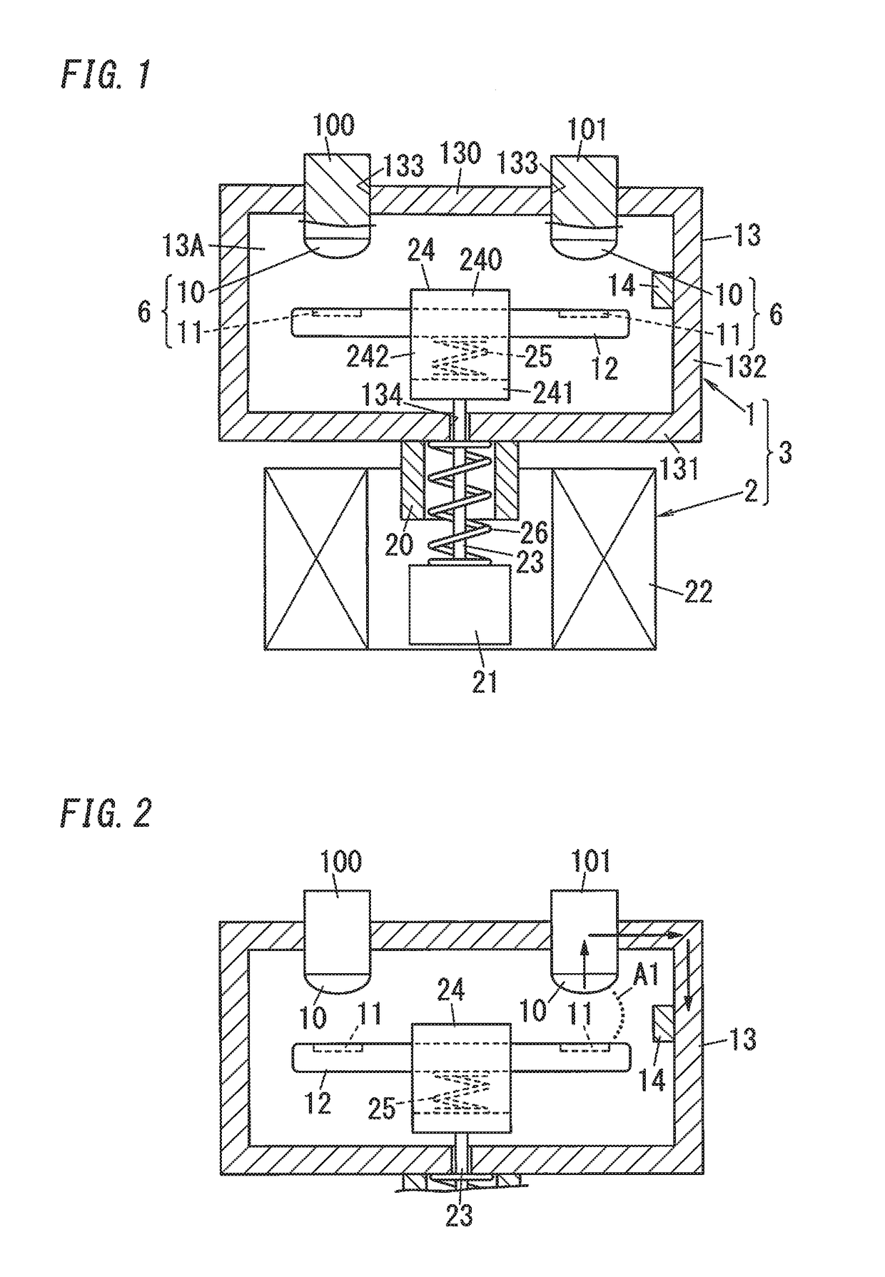
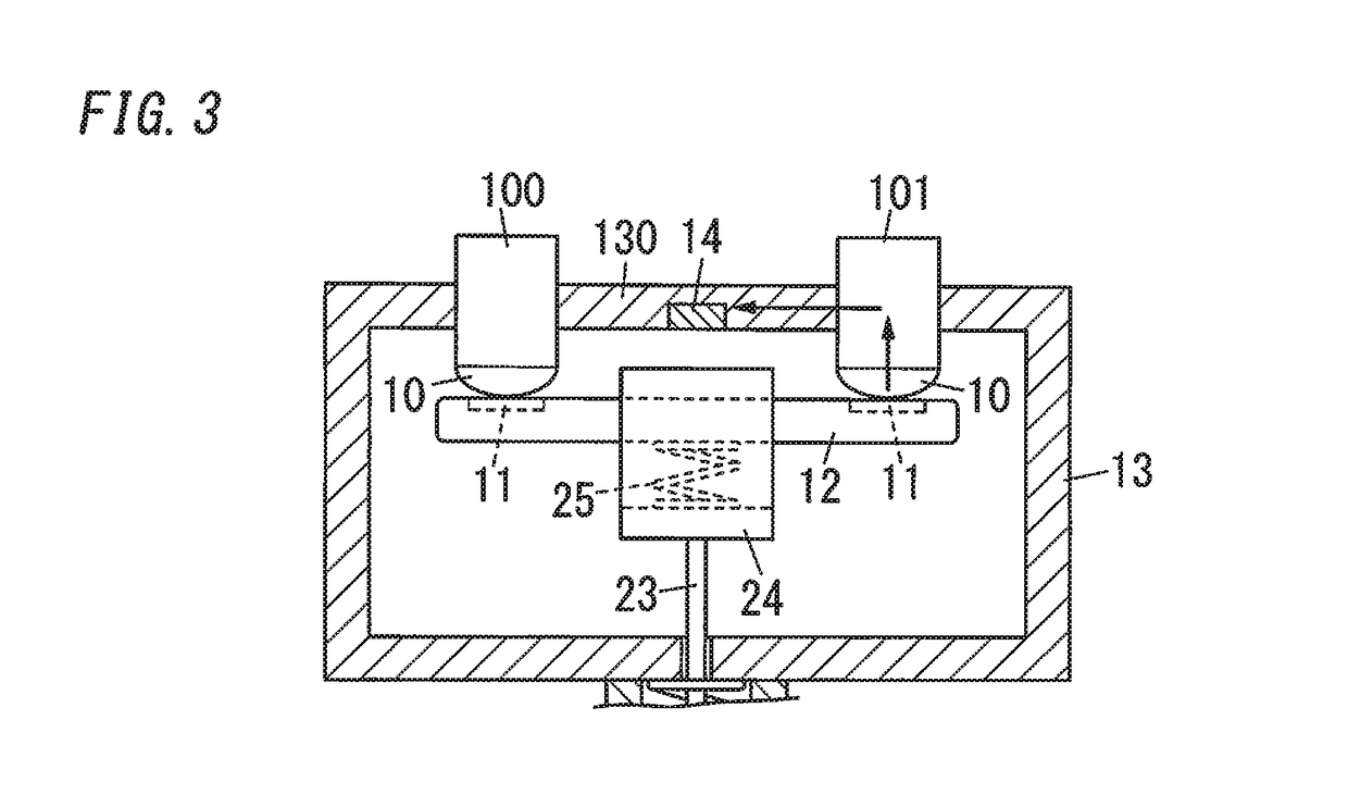
[0057]Hereinafter, a contact apparatus 1 of one embodiment of the present invention is described with reference to drawings. Note that, the contact apparatuses 1 described below are only examples of the present invention. The scope of the present invention is not limited to including only the below embodiment, and the embodiment may be modified in various ways in view of design or the like, provided that it is still inside the scope of the technical concept of the present invention. Further, in the following description, upward, downward, left and right directions shown in FIG. 1 correspond to upward, downward, left and right directions of the contact apparatus 1. In other words, in the following description, the upward and downward direction of the contact apparatus is defined by an axial direction of a shaft 23 described later. The upward direction of the contact apparatus is defined by a direction from the shaft 23 to a holder 24 described later, and the downward direction of the...

modification 1

(Modification 1)

[0094]FIG. 5A and FIG. 5B are schematic configuration diagrams of the contact apparatus 1 of Modification 1 of the present embodiment. The contact apparatus 1 of the present modification includes a magnetic field generator 15 for causing a magnetic field inside a space (the space 13A (shown in FIG. 1) inside the receptacle 13) including the fixed contact 10 and the movable contact 11, in addition to the components of the contact apparatus 1 of the embodiment. Other components of the present modification are the same as those of the embodiment, and the same components as the embodiment are designated by the same reference signs to avoid redundant explanations. Note that, FIG. 5B is a section of the contact apparatus 1 viewed from the upper side, and in the following explanation, an upward and downward direction of FIG. 5B corresponds to a forward and rearward direction of the modification.

[0095]The magnetic field generator 15 is constituted by a pair of magnets 150, w...

modification 2

(Modification 2)

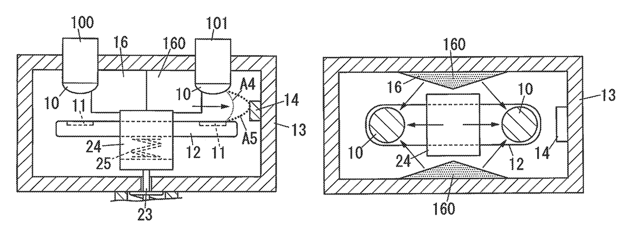
[0099]FIG. 6A and FIG. 6B are schematic configuration diagrams of the contact apparatus 1 of Modification 2 of the present embodiment. The contact apparatus 1 of the present modification includes a gas flow generator 16 for causing a flow of gas inside a space (the space 13A inside the receptacle 13) including the fixed contact 10 and the movable contact 11, in addition to the components of the contact apparatus 1 of the embodiment. Other components of the present modification are the same as those of the embodiment, and the same components as the embodiment are designated by the same reference signs to avoid redundant explanations. Note that, FIG. 6B is a section of the contact apparatus 1 viewed from the upper side, and in the following explanation, an upward and downward direction of FIG. 6B corresponds to a forward and rearward direction of the modification.

[0100]The gas flow generator 16 is constituted by protrusions 160 protruding inward from centers in the lef...


PUM


Abstract

The contact apparatus includes a fixed contact, a movable contact, and an arc extinguishing member. The movable contact is movable between a closed position where the movable contact is in contact with the fixed contact and an open position where the movable contact is separate from the fixed contact. The arc extinguishing member is for discharging an arc extinguishing gas offering a capacity for extinguishment of an arc, into a space containing the fixed contact and the movable contact.

Description

RELATED APPLICATIONS[0001]This application is the U.S. National Phase under 35 U.S.C. § 371 of International Application No. PCT / JP2014 / 004318, filed on Aug. 22, 2014 which in turn claims the benefit of Japanese Application No. 2013-178585, filed on Aug. 29, 2013; Japanese Application No. 2013-178588, filed Aug. 29, 2013; Japanese Application No. 2013-178589, filed Aug. 29, 2013; Japanese Application No. 2013-178586, filed Aug. 29, 2013; Japanese Application No. 2013-178590, filed Aug. 29, 2013 and Japanese Application No. 2013-178587, filed Aug. 29, 2013, the disclosures of which are incorporated by reference herein.TECHNICAL FIELD[0002]The present invention is, generally directed to contact apparatuses, and in particular directed to a contact apparatus for making and breaking conduction between contacts.BACKGROUND ART[0003]In the past, there has been proposed a contact apparatus including a pair of fixed contacts, and a pair of movable contacts movable between their closed positio...

Claims


Application Information

Patent Timeline
Patent Type & Authority Patents(United States)
IPC IPC(8): H01H33/78H01H9/30H01H50/38H01H9/34H01H9/36H01H50/00H01H50/02H01H50/54H01H1/66
CPCH01H33/78H01H1/66H01H9/302H01H9/34H01H50/00H01H50/38H01H50/54H01H9/36H01H2050/025H01H50/546
Inventor KANEMATSU, KENJIKIMOTO, SHINYAUOTOME, RIICHI
Owner PANASONIC INTELLECTUAL PROPERTY MANAGEMENT CO LTD
Why Eureka
Try Eureka