Electromagnetic relay

Active Publication Date: 2020-04-28
FUJITSU COMPONENENT LTD +1
View PDF33 Cites 4 Cited by
  • Summary
  • Abstract
  • Description
  • Claims
  • Application Information

AI Technical Summary

Benefits of technology

[0075]An aspect of this disclosure makes it possible to provide a relay that can quickly extinguish an arc even when an electric current flows in both directions, and makes it possible to improve the reliability of the relay.

Problems solved by technology

However, in electric vehicles and photovoltaic power generation systems, a large high-voltage current flows in both directions for charging and discharging.

Method used


Image

  • Electromagnetic relay
  • Electromagnetic relay
  • Electromagnetic relay

Examples


first embodiment

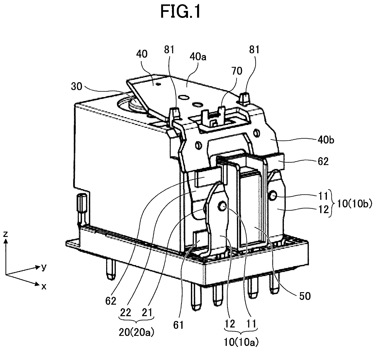
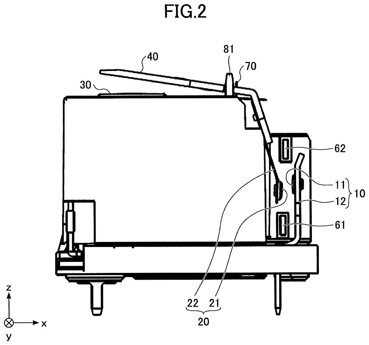
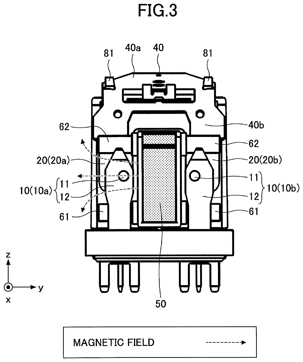
[0033]An electromagnetic relay (hereinafter referred to as “relay”) according to a first embodiment is described with reference to FIGS. 1 through 3. The relay of the first embodiment includes a fixed contact part 10 including a fixed contact 11 and a fixed terminal 12, and a movable contact part 20 including a movable contact 21 and a movable spring 22. In the first embodiment, the relay includes two pairs of the fixed contact part 10 and the movable contact part 20. In the descriptions below, one of the two pairs including a fixed contact part 10a and a movable contact part 20a is referred to as a first contact pair, and the other one of the two pairs including a fixed contact part 10b and a movable contact part 20b is referred to as a second contact pair.

[0034]An electromagnet 30 is provided on the side of the relay where the movable contact parts 20 are provided. An armature 40 is provided near an end of the electromagnet 30. The armature 40 is bent into a shape like an inverted...

second embodiment

[0058]Next, a second embodiment is described. As illustrated in FIGS. 18 and 19, a relay of the second embodiment includes a permanent magnet 150 that is long in z direction. For example, as illustrated in FIG. 20, if a permanent magnet 51 that is short in the z direction is used, a generated arc is stretched toward the permanent magnet 51 as indicated by a dashed double-dotted arrow and may damage the movable spring 22 and the armature 40 near the permanent magnet 51.

[0059]In the second embodiment, the permanent magnet 150 that is long in z direction is used, and the fixed contact 11 and the movable contact 21 are disposed in positions that are shifted in −z direction from the center of the permanent magnet 150 in the longitudinal direction. With this configuration, as indicated by a dashed double-dotted arrow in FIG. 19, a generated arc is first stretched in a direction away from the permanent magnet 150 and contacts the second arc extinguishing plate 62 at a position away from th...

third embodiment

[0065]Next, a third embodiment is described. In the embodiment, an armature is formed of a magnetic material with high permeability and has a certain thickness to provide strength.

[0066]As indicated by an arrow A in FIG. 22, the magnetic flux from the permanent magnet 150 passes through the second side 40b of the armature 40. Therefore, the magnetic field is weakened in an area higher than the fixed contact 11 and the movable contact 21 in +z direction, and the effect of the magnetic field to stretch the arc may be reduced.

[0067]When the movable contact 21 moves away from the fixed contact 11, the second side 40b of the armature 40 contacts a backstop 93 formed on the insulation case 90 while the restoring force of the spring 70 is maintained to position the movable contact 21 attached to the movable spring 22 and to suppress the return bounce of the movable contact 21.

[0068]The second side 40b of the armature 40 that is thicker than the movable spring 22 and has a greater thermal c...


PUM


Abstract

An electromagnetic relay includes a fixed contact part including a fixed terminal and a fixed contact connected to the fixed terminal, a movable contact part including a movable contact spring and a movable contact connected to the movable contact spring, an armature to which the movable contact part is connected, an electromagnet configured to move the armature, a magnet configured to stretch an arc generated between the fixed contact and the movable contact, and a first arc extinguishing plate and a second arc extinguishing plate configured to extinguish the stretched arc. The fixed contact and the movable contact are disposed between the first arc extinguishing plate and the second arc extinguishing plate. The magnet is disposed between a first pair of the fixed contact part and the movable contact part and a second pair of the fixed contact part and the movable contact part.

Description

CROSS-REFERENCE TO RELATED APPLICATION[0001]The present application is based upon and claims the benefit of priority of Japanese Patent Application No. 2016-252656, filed on Dec. 27, 2016, the entire contents of which are incorporated herein by reference.BACKGROUND OF THE INVENTION1. Field of the Invention[0002]An aspect of this disclosure relates to an electromagnetic relay.2. Description of the Related Art[0003]An electromagnetic relay is an electronic component that turns on and off electric power using an electromagnet. When an electromagnetic relay is used for high-voltage power or direct-current power, an arc may be generated between contacts and the arc may reduce the life of the electromagnetic relay (see, for example, Takuya HARA, Junya SEKIKAWA, “Influence of Contact Material Vapor on Thermodynamic and Transport Properties of Arc Plasmas Occurring between Ag and Ag / SnO2 contact pairs”, IEICE TRANSACTIONS on Electronics Vol. E97-C No. 9 pp. 863-866, 2014 / 09 / 01).[0004]In a k...

Claims


Application Information

Patent Timeline
Patent Type & Authority Patents(United States)
IPC IPC(8): H01H9/30H01H50/18H01H9/36H01H33/59H01H9/34H01H50/14H01H50/38H01H9/44H01H50/54H01H50/26H01H1/20
CPCH01H9/36H01H50/38H01H33/596H01H9/34H01H50/14H01H9/443H01H50/18H01H1/2066H01H50/26H01H50/546H01H50/54H01H50/16H01H9/30
Inventor IWAMOTO, DAIEISEKIKAWA, JUNYA
Owner FUJITSU COMPONENENT LTD
Why Eureka
Try Eureka