Power circuit breaker

Active Publication Date: 2017-01-10
BRAUNSCHWEIG UNIVERSITY OF TECHNOLOGY
View PDF15 Cites 4 Cited by
  • Summary
  • Abstract
  • Description
  • Claims
  • Application Information

AI Technical Summary

Benefits of technology

[0018]For further increase in the operational reliability, it has proven useful when a plurality of secondary electrodes are present, at least indivi

Problems solved by technology

In particular when the electrodes are separated, there is a high likelihood that an undesired arc will occur.
Even when this arc is extinguished in the meantime, there is the danger that it can reignite and indeed contin

Method used


Image

  • Power circuit breaker
  • Power circuit breaker
  • Power circuit breaker

Examples


Embodiment Construction

[0033]Identical and similar means are provided in the figures with identical reference numbers. A repeated description occurs only insofar as it seems necessary for understanding the invention or exemplary embodiments. Although the exemplary embodiments describe the switching of high voltage, it is pointed out once again that the power circuit breaker according to the invention is suitable for the switching of electrical voltages of any value.

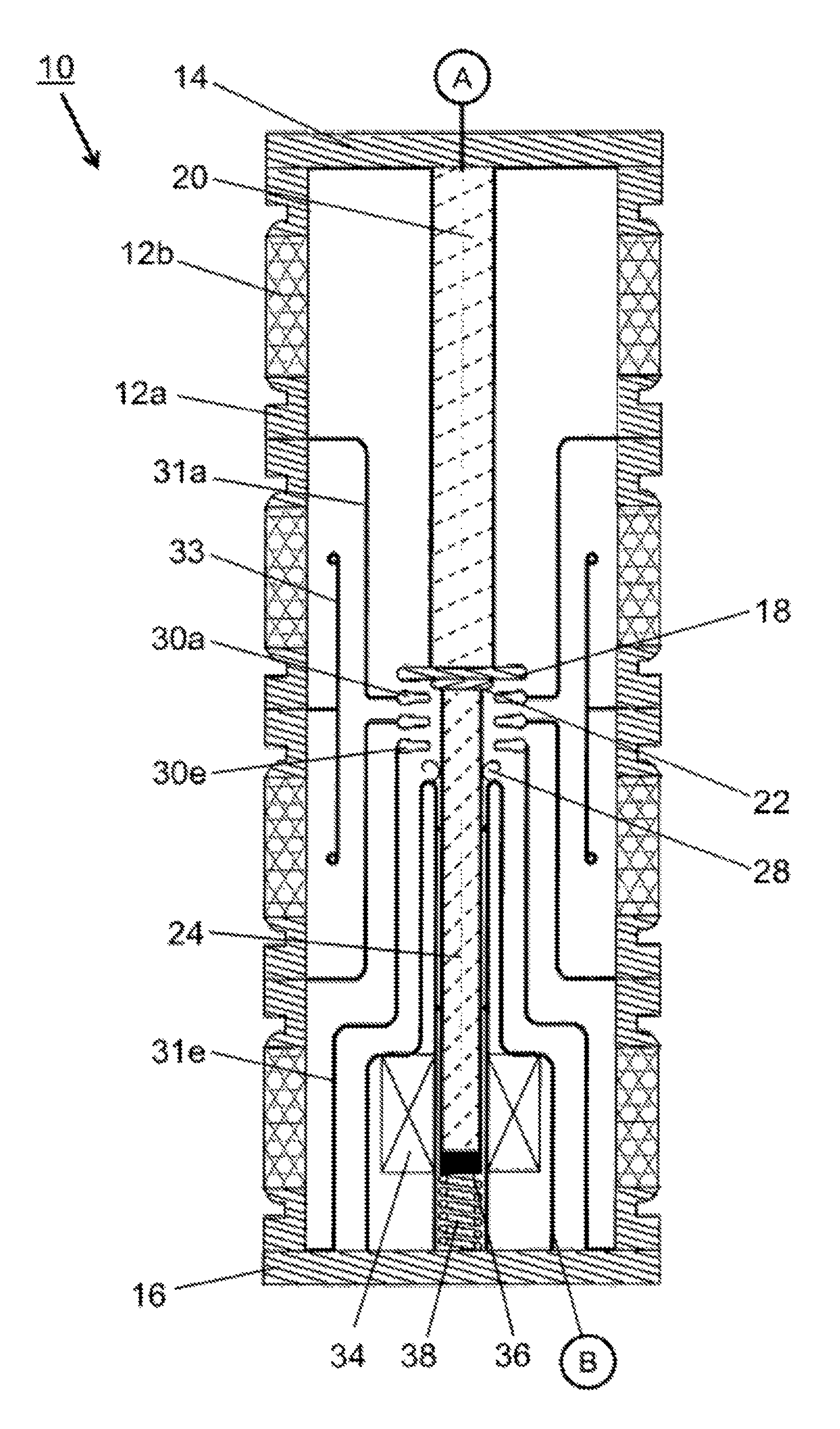
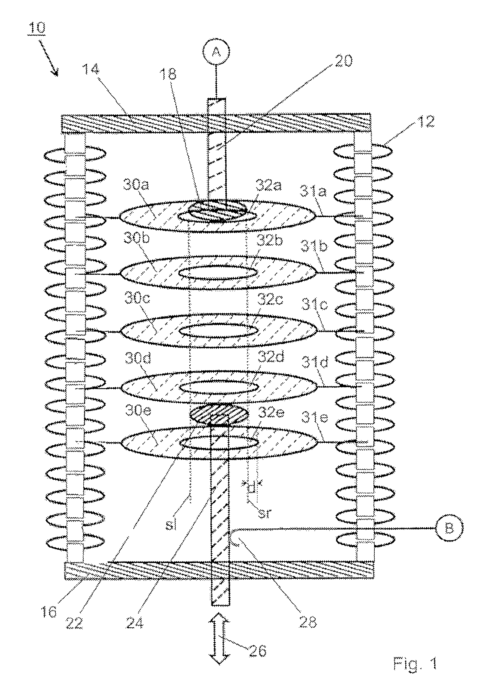
[0034]FIG. 1 shows a symbolic illustration of a preferred power circuit breaker 10, which is suitable for switching direct voltages of up to 100 kV and more. It is preferably designed as a vacuum circuit breaker in which a pressure of approximately 10−6 mbar usually prevails. The preferred embodiment is essentially circularly symmetrical or cylindrically symmetrical in design. This means that the housing of the power circuit breaker 10 comprises an essentially cylindrically shaped insulator 12 as well as a top end plate 14 and a bottom end plat...


PUM


Abstract

The invention relates to a power circuit breaker that is suitable for switching electrical voltages. The power circuit breaker according to the invention comprises two main electrodes, to each of which a respective pole of the voltage to be switched can be connected. During the switching process, at least one of said main electrodes follows a switching path. The power circuit breaker is characterized in that secondary electrodes are additionally provided, which protrude into the vicinity of the switching path and are designed and arranged in such a way that arcs can be produced (a) between the main electrodes and the secondary electrodes and (b) between the individual secondary electrodes during the switching process. The power circuit breaker according to the invention can be advantageously used in vehicles and in ultra-high-voltage AC and HVDC (high-voltage direct current) transmission systems and causes arcs to be extinguished as early as possible during the switching process.

Description

TECHNICAL FIELD[0001]The present invention relates to a power circuit breaker that is suitable for switching electrical voltages or electrical currents and powers.BACKGROUND OF THE INVENTION[0002]Usually, a power circuit breaker contains two electrodes, to each of which, in operation, a respective pole of the voltage to be switched is applied. In particular when the electrodes are separated, there is a high likelihood that an undesired arc will occur. Even when this arc is extinguished in the meantime, there is the danger that it can reignite and indeed continue to do so until the separating gap is sufficiently large.[0003]In order to ensure that such arcs are extinguished insofar as possible, the insulating gas SF6 (sulfur hexafluoride) is utilized in many known high-voltage power circuit breakers. However, this is a very strong greenhouse gas, which can escape into the atmosphere, particularly in the event of leakage and after the end of the service life.[0004]Therefore, in partic...

Claims


Application Information

Patent Timeline
IPC IPC(8): H01H9/36H01H33/08H01H33/664H01H33/16H01H33/20H01H33/59H01H33/10H01H23/08
CPCH01H9/36H01H33/08H01H33/10H01H33/164H01H33/20H01H33/596H01H33/664H01H33/6647
Inventor ERMEL, VLADIMIRKURRAT, MICHAEL
Owner BRAUNSCHWEIG UNIVERSITY OF TECHNOLOGY
Why Eureka
Try Eureka