Inductive coupling of pulses from piezoelectric device

a piezoelectric device and inductive coupling technology, applied in the direction of generators/motors, instruments, transportation and packaging, etc., to achieve the effect of facilitating greater functionality of tire electronics, reducing adverse effects resulting from the high vibration environment of tires, and improving system operation reliability

Active Publication Date: 2009-05-28
MICHELIN RECH & TECH SA
View PDF23 Cites 31 Cited by
  • Summary
  • Abstract
  • Description
  • Claims
  • Application Information

AI Technical Summary

Benefits of technology

[0013]Another advantage of the present subject matter is that a tire monitoring system is provided that improves the operational reliability of the system by reducing adverse effects resulting for the high vibration environment of a tire. For example, no direct-wired connection from the tire rotation sensor to the tire electronics is required.
[0014]Yet another advantage of optional features the present subject matter is that there are fewer limitations regarding the type and amount of electronic equipment capable of utilization within tire and wheel assembly structures. Tire electronics powered by conventional methods are often limited to ultra-low power devices. Devices in accordance with the disclosed technology are not necessarily subject to such extreme power limitations. This advantage further facilitates greater functionality of tire electronics, as more components and / or higher-level equipment may potentially be utilized.
[0015]A still further advantage of the present subject matter is that the disclosed system and method for sensing tire rotation and rotation related parameters may be used in accordance with a variety of existing applications. Measurement capabilities, monitoring and warning systems, vehicle feedback systems, and asset tracking potential may be possible for applications such as commercial truck fleets, airplanes, and mining / earthmover equipment.

Problems solved by technology

In addition, although batteries and battery-operated devices may be incorporated with aspects of the present subject matter, many complications regarding tire electronics that are solely powered by batteries may be obviated in accordance with optional features of the disclosed technology through the employment of the tire rotation sensitive piezoelectric device as a source of operating potential for the tire electronics.

Method used


Image

  • Inductive coupling of pulses from piezoelectric device
  • Inductive coupling of pulses from piezoelectric device
  • Inductive coupling of pulses from piezoelectric device

Examples


Embodiment Construction

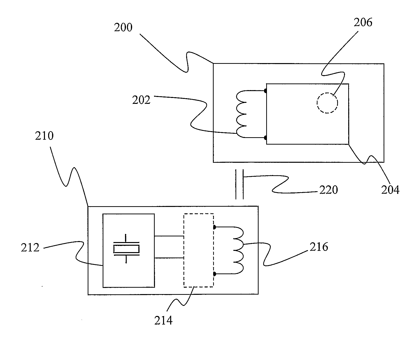
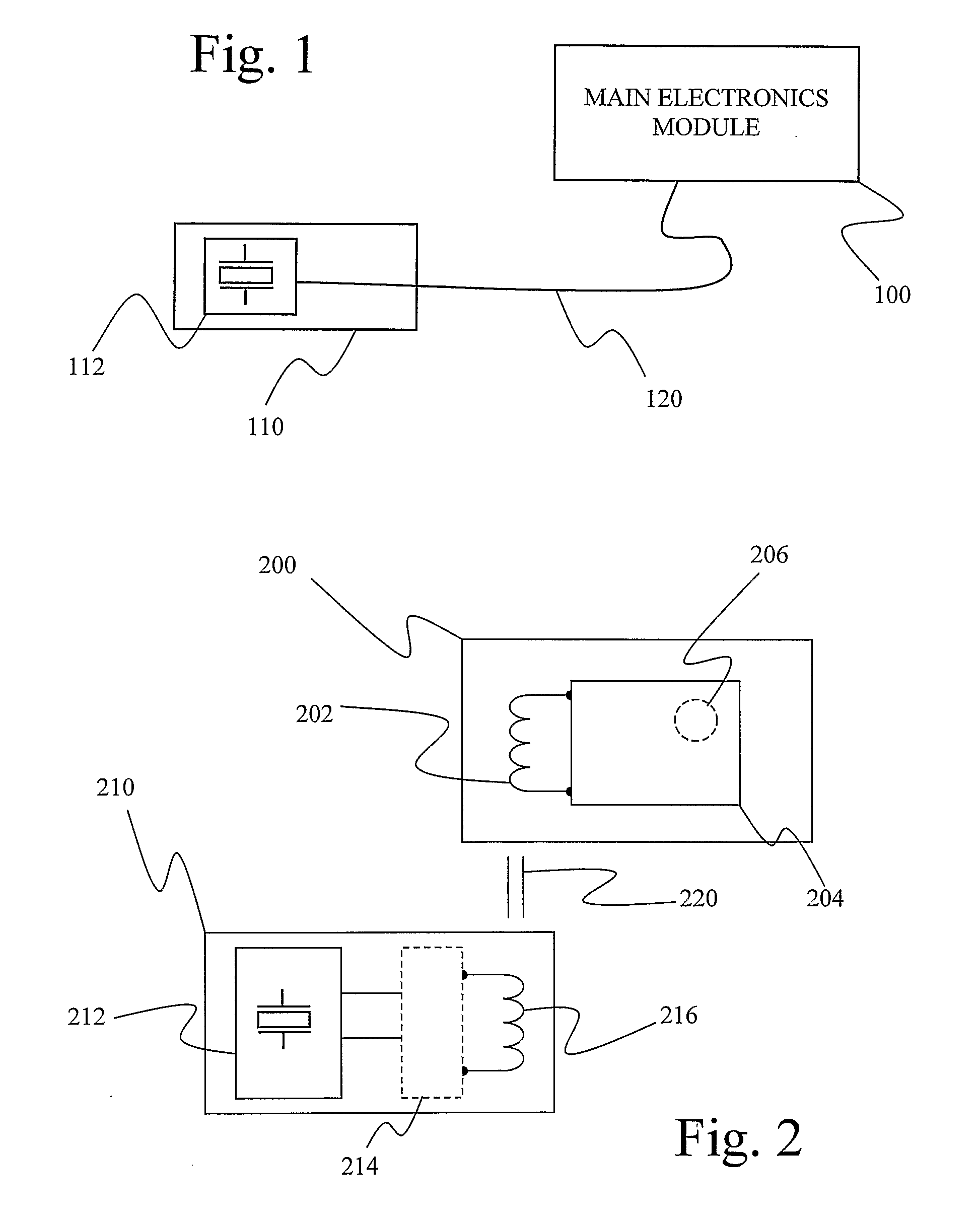
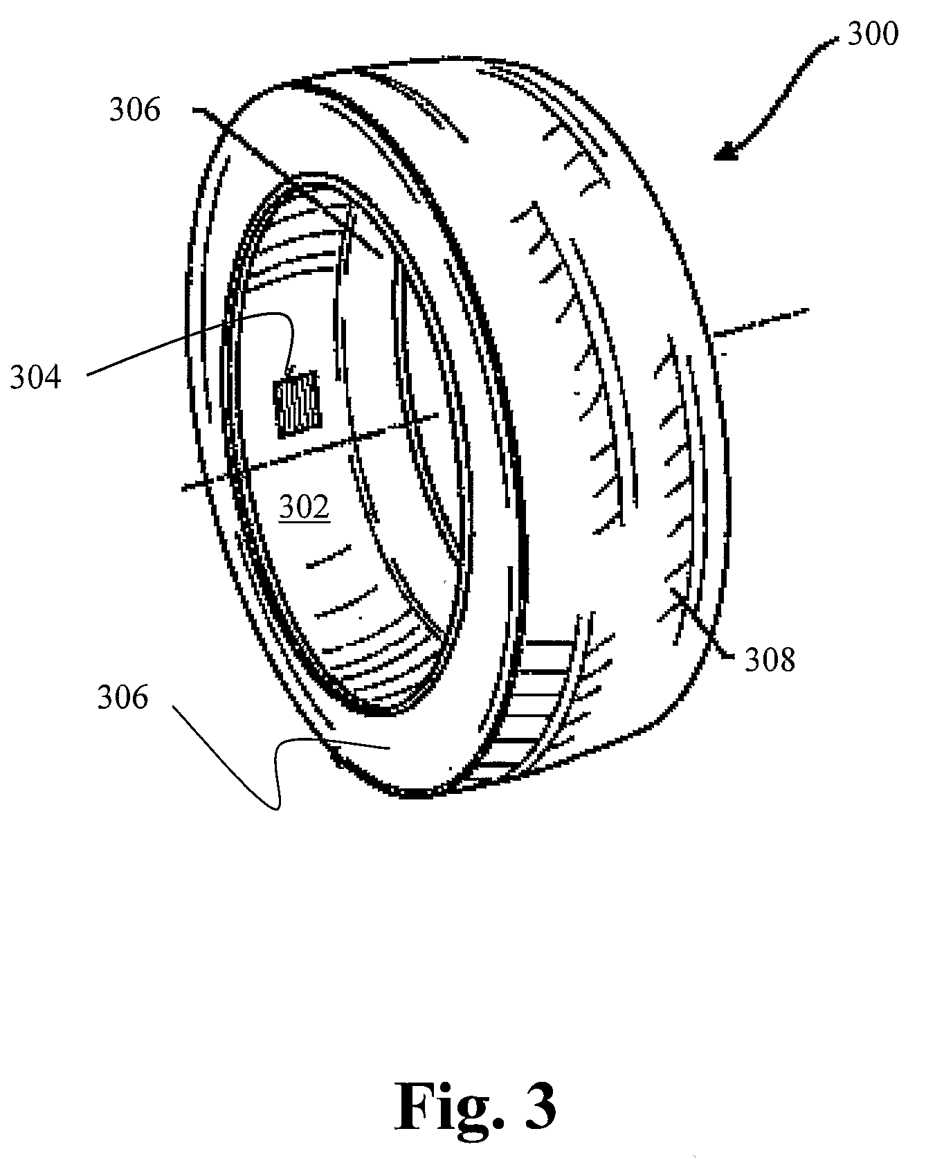
[0025]As discussed in the Summary of the Invention section, the present subject matter is particularly concerned with an improved system and methodology for transmitting tire rotation related signals to electronic systems integrated within a tire structure.

[0026]Selected combinations of aspects of the disclosed technology correspond to a plurality of different embodiments of the present invention. It should be noted that each of the exemplary embodiments presented and discussed herein should not insinuate limitations of the present subject matter. Features or steps illustrated or described as part of one embodiment may be used in combination with aspects of another embodiment to yield yet further embodiments. Additionally, certain features may be interchanged with similar devices or features not expressly mentioned which perform the same or similar function.

[0027]Reference will now be made in detail to the presently preferred embodiments of the subject inductive coupling apparatus a...


PUM

PropertyMeasurementUnit
widthaaaaaaaaaa
energyaaaaaaaaaa
operating poweraaaaaaaaaa

Abstract

Discloses is apparatus and methodology for inductively coupling tire rotations related signals to a tire electronics module (200) associated with a tire. The tire electronics module (200) is configured to receive the tire rotation related signals (220) through inductive transmission from a signal transmission module (210) that includes at least a piezoelectric element (212) and a transmitter inductor (216). The signal transmitter module (210) and the tire electronics module (200) may be physically separated from each other and may be separately or collectively encased in a protective coating.

Description

FIELD OF THE INVENTION[0001]The present technology relates to the field of tire electronics devices and the supplying of signals to such devices. More particularly, the present technology relates to inductively transmitting data to such devices from a piezoelectric device.BACKGROUND OF THE INVENTION[0002]The incorporation of electronic devices with pneumatic tire structures yields many practical advantages. Tire electronics may include sensors and other components for obtaining information regarding various physical parameters of a tire, such as temperature, pressure, number of tire revolutions, vehicle speed, number of rotations at speed, temperature at speed and other physical and operational parameters as well as manufacturing information such as name of manufacturer, manufacturing location, date of manufacture, etc. Such performance information may become useful in tire monitoring and warning systems, and may even potentially be employed with feedback systems to regulate proper ...

Claims


Application Information

Patent Timeline
Patent Type & Authority Applications(United States)
IPC IPC(8): H01F38/14H01L41/113H02N2/18H02J7/32
CPCB60C23/0411
Inventor TYNDALL, PATRICK A.GRAMLING, FRANK E.
Owner MICHELIN RECH & TECH SA
Why Eureka
Try Eureka