
Heat dissipation apparatus for medium-voltage drive

a medium-voltage drive and heat dissipation apparatus technology, which is applied in the direction of cooling/ventilation/heating modification, semiconductor device details, semiconductor/solid-state device details, etc., can solve the problems of adversely affecting the performance and service life of power devices, increase leakage inductance, and low efficiency, so as to reduce the electrical connection distance, reduce the leakage inductance, and improve the heat dissipation efficiency of each power device

Inactive Publication Date: 2013-04-04
DELTA ELECTRONICS (SHANGHAI) CO LTD
View PDF11 Cites 31 Cited by
  • Summary
  • Abstract
  • Description
  • Claims
  • Application Information

AI Technical Summary

Benefits of technology

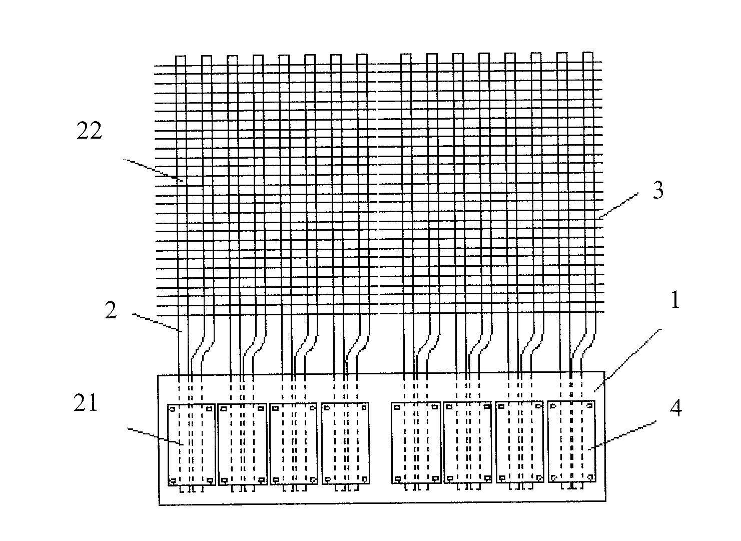
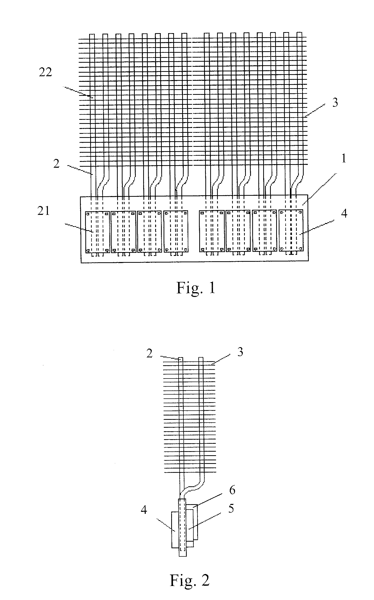
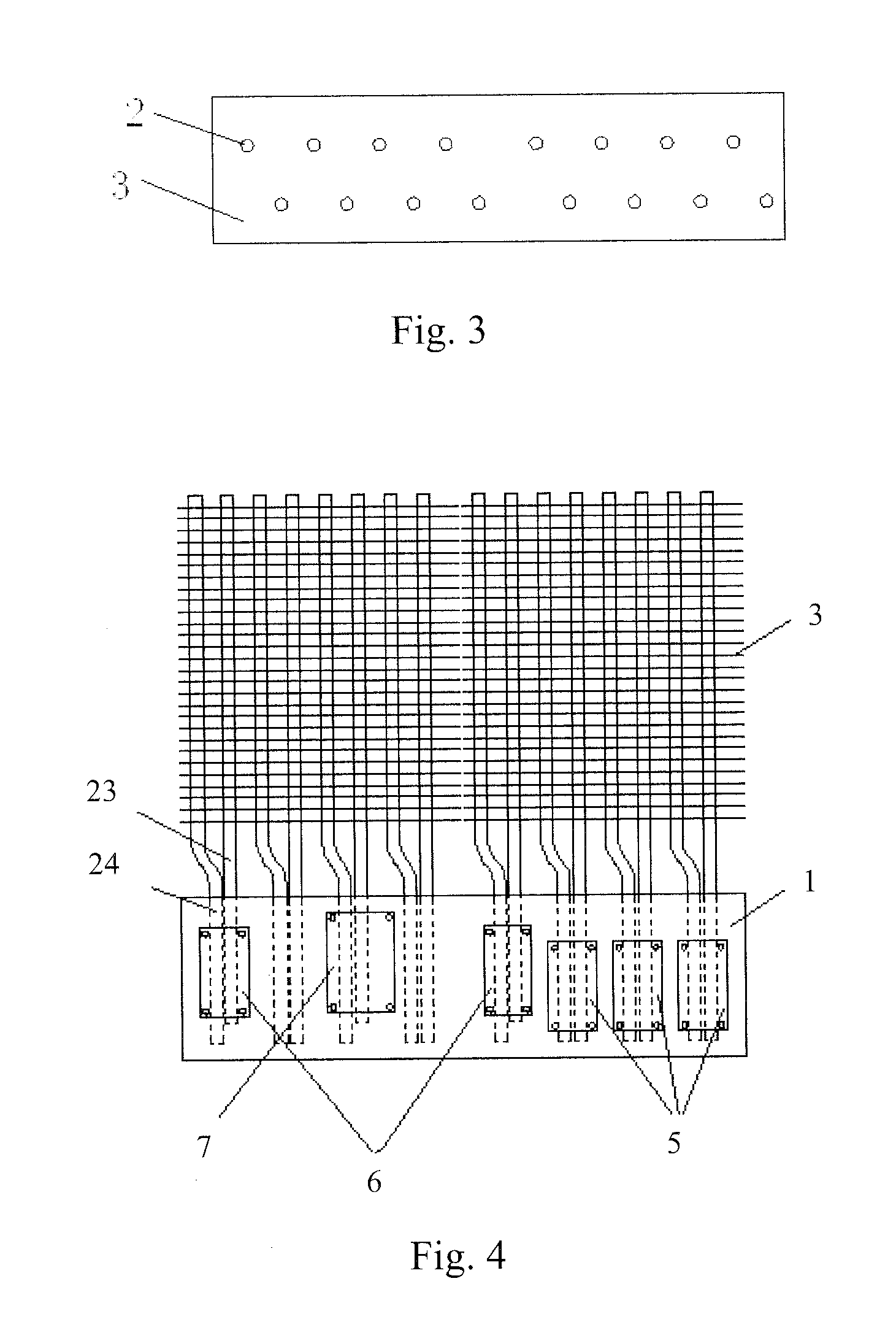
The heat dissipation apparatus described in this patent improves heat dissipation efficiency for power devices by arranging heat pipes and fins in a triangle staggered arrangement. The arrangement of the power devices on the heat-dissipating substrate is compact, reducing electrical connection distance and leakage inductance. Furthermore, the placement of high-frequency and low-frequency circuits onto different sides of the substrate isolates them, reducing interference and improving the operation reliability of the drive.

Problems solved by technology

However, the power devices often generate massive heat when being frequently switched between on and off, and thus a heat dissipation apparatus is needed to be disposed correspondingly to effectively dissipate heat generated from the power devices, thereby ensuring the normal operation of the medium-voltage drive.
On the other hand, the larger interval between the power devices increases the electrical connection distance, thus resulting in the increase of leakage inductance and low efficiency, further adversely affecting the performance and service life of the power devices.

Method used


Image

  • Heat dissipation apparatus for medium-voltage drive
  • Heat dissipation apparatus for medium-voltage drive
  • Heat dissipation apparatus for medium-voltage drive

Examples


Embodiment Construction

[0025]Hereinafter, specific embodiments of the present invention are sufficiently explained with reference to the drawings.

[0026]In order to make the description of the present invention more detailed and more comprehensive, various embodiments are described below with reference to the accompanying drawings, wherein like reference numerals refer to like elements throughout. However, these embodiments are not intended to limit the present invention. The description of structure operation does not mean to limit its implementation order. Any device with equivalent functions that is produced from a structure formed by recombination of elements shall fall within the scope of the present invention.

[0027]The drawings are only illustrative and are not made according to the original size. In addition, well-known elements and steps are not described in the embodiments to avoid causing unnecessary limitations to the present invention.

[0028]FIG. 1 is a front view of a heat dissipation apparatus...


PUM


Abstract

A heat dissipation apparatus is suitable for dissipating heat from heat-generating elements in a medium-voltage drive. The heat dissipation apparatus comprises: a heat-dissipating substrate, wherein the heat-generating elements are placed on at least one of a first surface and a second surface of the heat-dissipating substrate; at least one heat pipe group each of which includes a plurality of heat pipes, each heat pipe having an evaporation section and a condensation section, wherein the evaporation section is buried in an inner layer of the heat-dissipating substrate for absorbing heat from the heat-generating elements; and a plurality of fins arranged to be intersected with each heat pipe and connected to the condensation sections of the heat pipes, so as to transfer the heat released from the condensation sections to air. The contact portions between the heat pipe group and the fins are arranged in triangle staggered arrangements.

Description

RELATED APPLICATIONS[0001]This application claims priority to Chinese Application Serial Number 201110303758.9, filed Sep. 29, 2011, which is herein incorporated by reference.BACKGROUND[0002]1. Field of Invention[0003]The present invention relates to a heat dissipation apparatus, and more particularly to a heat dissipation apparatus for a medium-voltage drive.[0004]2. Description of Related Art[0005]Nowadays, a medium-voltage drive is widely applied in a number of power and electronic circuits. The medium-voltage drive is a power control apparatus, which changes frequency by turning on or off semiconductor power devices, so as to implement the functions such as soft start, variable frequency speed control, power factor changing and over-current / over-voltage / overload protection. However, the power devices often generate massive heat when being frequently switched between on and off, and thus a heat dissipation apparatus is needed to be disposed correspondingly to effectively dissipat...

Claims


Application Information

Patent Timeline
Patent Type & Authority Applications(United States)
IPC IPC(8): H05K7/20
CPCH01L23/427F28D15/0275H01L2924/0002H01L2924/00
Inventor TONG, AI-XINGGAN, HONG-JIAN
Owner DELTA ELECTRONICS (SHANGHAI) CO LTD
Learn More