Oil separator and cooling-cycle apparatus using the same

a technology of oil separator and cooling cycle, which is applied in the direction of liquid degasification, refrigeration machines, separation processes, etc., can solve the problems of low degree of oil separation efficiency, complicated installation operation, and increased manufacturing costs, so as to achieve the effect of separating oil from gas

Inactive Publication Date: 2006-06-01
LG ELECTRONICS INC
View PDF14 Cites 28 Cited by
  • Summary
  • Abstract
  • Description
  • Claims
  • Application Information

AI Technical Summary

Benefits of technology

[0019] Therefore, the present invention has been made in view of the above problems, and it is an o

Problems solved by technology

The above described conventional oil separator 10 having a configuration in that the filtering member 16 is mounted therein to filter the oil from the gaseous refrigerant, however, suffers from increased manufacturing costs and complicated installation operation due to the existence of the filtering member 16, and also has a li

Method used


Image

  • Oil separator and cooling-cycle apparatus using the same
  • Oil separator and cooling-cycle apparatus using the same
  • Oil separator and cooling-cycle apparatus using the same

Examples


first embodiment

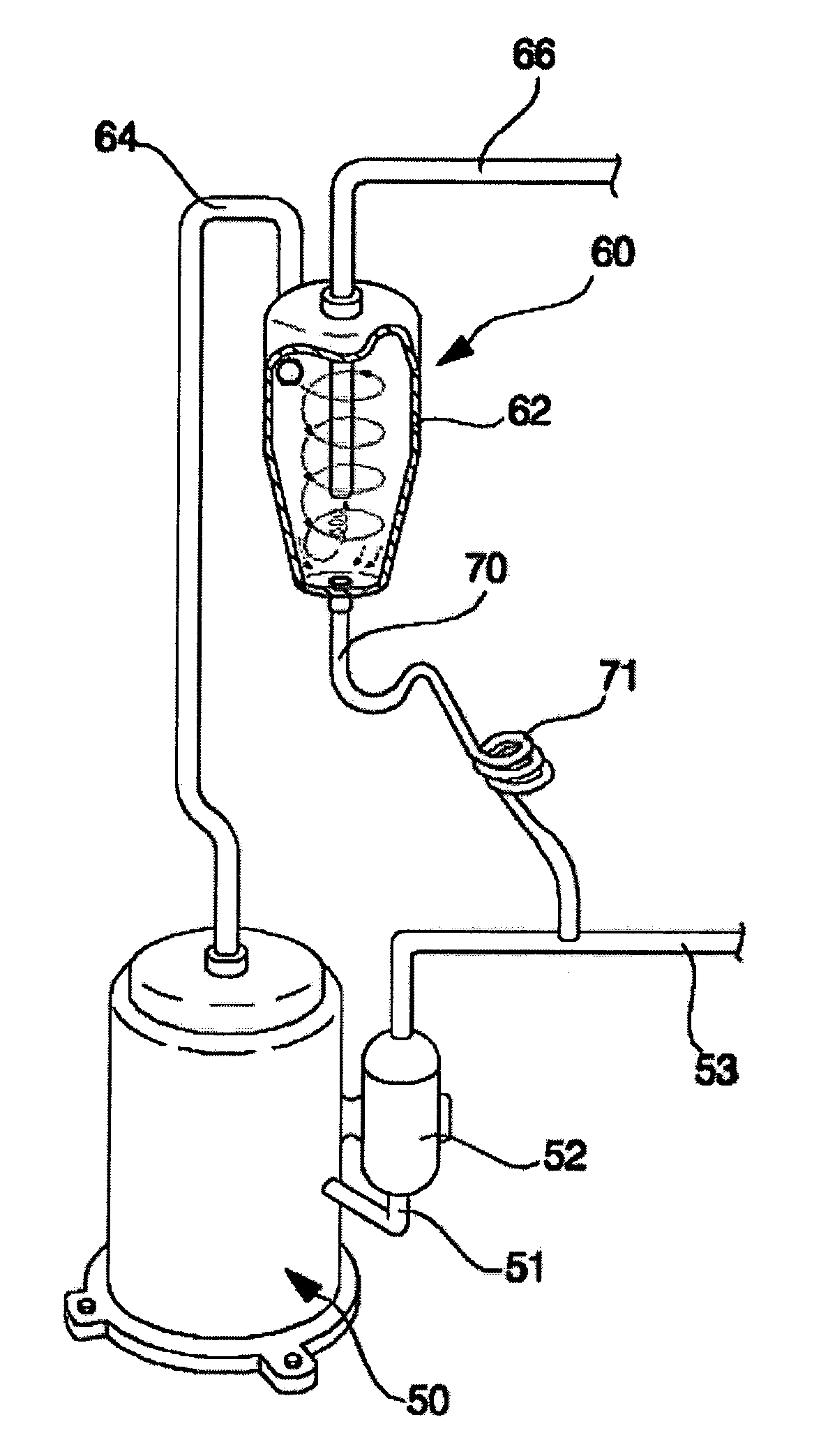
[0057]FIGS. 4 and 5 are a longitudinal sectional view and a cross sectional view, respectively, illustrating an oil separator in accordance with the present invention.

[0058] As shown in FIGS. 4 and 5, the casing 62 of the oil separator 60 includes a cylindrical portion 62a to which the inflow tube 64 is inserted, and a conical portion 62b defined under the cylindrical portion 62a.

[0059] The inflow tube 64 is a straight tube eccentrically inserted in the casing 62 for supplying the oil and the gaseous refrigerant into the casing 62 in a direction deviating from a casing center axis. Preferably, the inflow tube 64 is inserted into the casing 62 to come into contact with an inner periphery of the casing 62.

[0060] With such an insertion structure, an angle a formed by an imaginary line A-A, along which the inflow tube 64 is inserted into the casing 62, and an imaginary line B-B connecting between a refrigerant and oil outlet end 65 of the inflow tube 64 and a center of the casing 62 i...

second embodiment

[0073]FIG. 6 is a cross sectional view illustrating an oil separator in accordance with the present invention.

[0074] As shown in FIG. 6, the oil separator 60′ of the second embodiment comprises an inflow tube 64′ in the form of a bent tube. That is, the inflow tube 64′ has a bent refrigerant and oil outlet end 65′.

[0075] In the bent tube 64′, a bending angle β of the outlet end 65′ is greater than 0° and less than 90°.

[0076] The bent tube 64′ is inserted into the casing 62 to extend toward the casing center axis.

third embodiment

[0077]FIG. 7 is a longitudinal sectional view illustrating an oil separator in accordance with the present invention.

[0078] As shown in FIG. 7, the oil separator 60″ of the third embodiment comprises a refrigerant outflow tube 66′, which is inserted horizontally into the casing 62 through a peripheral wall thereof, and has a bent refrigerant inlet end 67′.

[0079] The oil separator of the third embodiment further comprises an inflow tube 64″, which is inserted vertically into the casing 62 through the upper surface of the casing 62, and has a bent outlet 65″.

[0080] As apparent from the above description, an oil separator and a cooling-cycle apparatus using the same according to the present invention has several advantages as follows:

[0081] First, according to the oil separator of the present invention, an inflow tube is connected to a casing of the oil separator to supply oil and gaseous refrigerant into the casing, so as to cause them to be separated from each other while flowing ...


PUM

PropertyMeasurementUnit
Angleaaaaaaaaaa
Angleaaaaaaaaaa
Angleaaaaaaaaaa

Abstract

Disclosed herein are an oil separator and a cooling-cycle apparatus using the oil separator. To a casing of the separator is connected an inflow tube to supply gaseous refrigerant and oil into the casing for allowing them flowing in a swirl pattern, thereby being separated from each other in a cyclone separation manner. Such a separation manner results in an improved oil separation efficiency.

Description

BACKGROUND OF THE INVENTION [0001] 1. Field of the Invention [0002] The present invention relates to an oil separator for separating oil from gas and a cooling-cycle apparatus using the oil separator, and more particularly, to an oil separator for separating oil from gas in a cyclone separation manner, and a cooling-cycle apparatus using the oil separator. [0003] 2. Description of the Related Art [0004] As well known to those skilled in the art, a cooling-cycle apparatus is an apparatus installed in an air conditioner, refrigerator, etc. for cooling or warming a room, or keeping food at low temperatures. [0005]FIG. 1 is a diagram of a conventional cooling-cycle apparatus. [0006] As shown in FIG. 1, the cooling-cycle apparatus comprises a compressor 2, a condenser 4, an expander 6, an evaporator 8, and refrigerant conveyance tubes 9. The compressor 2 compresses a gaseous refrigerant having a low-temperature and low-pressure to a high-temperature and high-pressure gas, and the condens...

Claims


Application Information

Patent Timeline
IPC IPC(8): F25B43/02F25B43/00B01D19/00
CPCB01D19/0057F25B43/02F25B2400/02F25B2500/01F25B43/00
Inventor CHANG, SEUNG YONGLEE, YOON BEENKIM, SUNG CHUNCHANG, SE DONG
Owner LG ELECTRONICS INC
Why Eureka
Try Eureka