Operating method and actuation device for a piston pump

Active Publication Date: 2018-01-25
ROBERT BOSCH GMBH
View PDF16 Cites 5 Cited by
  • Summary
  • Abstract
  • Description
  • Claims
  • Application Information

AI Technical Summary

Benefits of technology

[0026]In a further form of embodiment, the coil is connected in parallel with a current path, which comprises an additional semiconductor switch and a diode. With respect to the direction of current flow from the supply voltage potential to the ground potential, the diode is arranged in a blocking direction. The additional semiconductor switch, further to the switch-out of the semiconductor switch for the application of the supply voltage potential, permits the isolation of a freewheeling circuit for the flow of current in the coil. This permits the slow decay of current in the coil.
[0027]In a further form of embodiment, a Zener diode is connected in parallel with the semiconductor switch for the appli

Problems solved by technology

This results in a disturbance to the uniformity of th

Method used


Image

  • Operating method and actuation device for a piston pump
  • Operating method and actuation device for a piston pump
  • Operating method and actuation device for a piston pump

Examples


Embodiment Construction

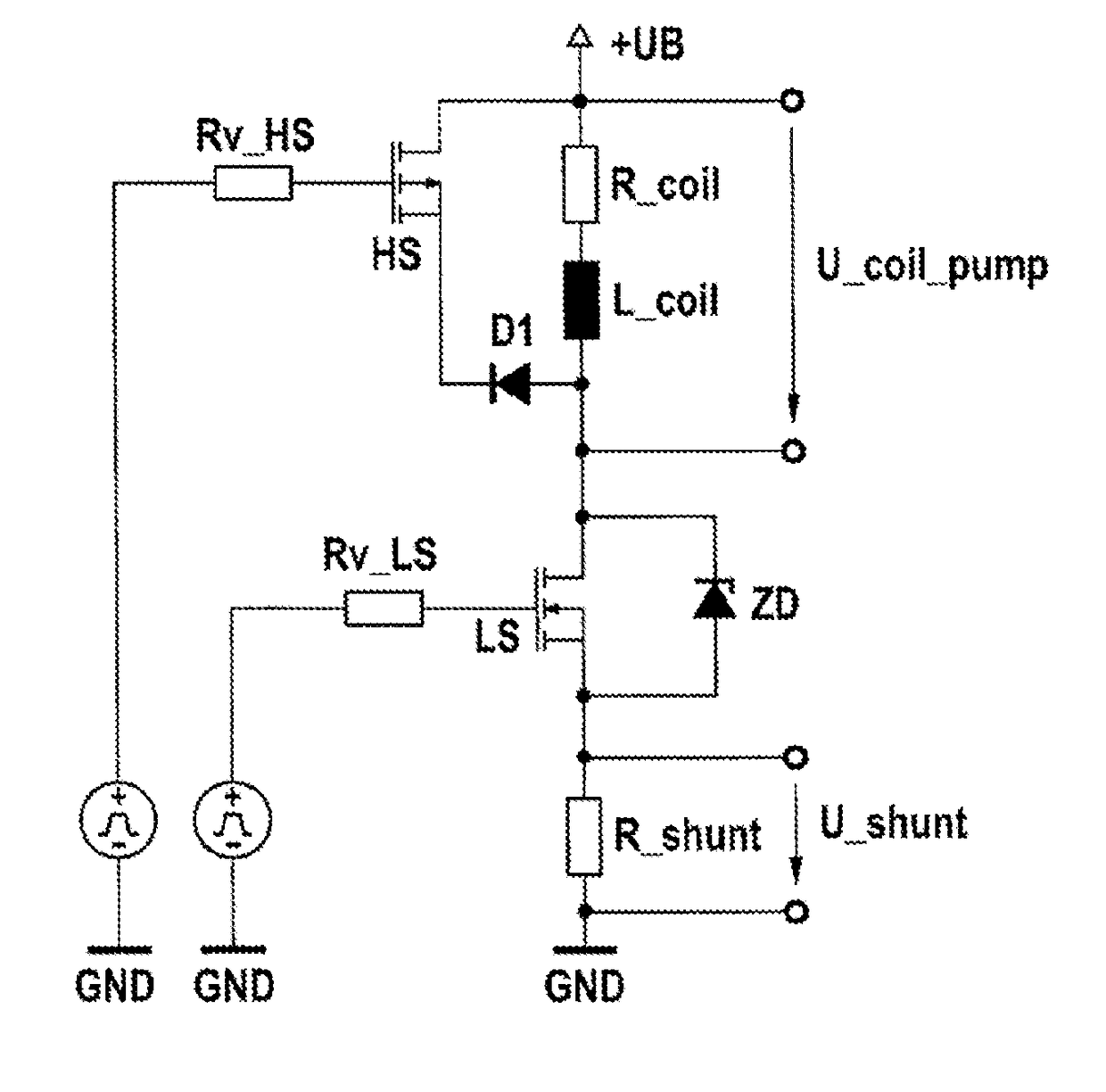
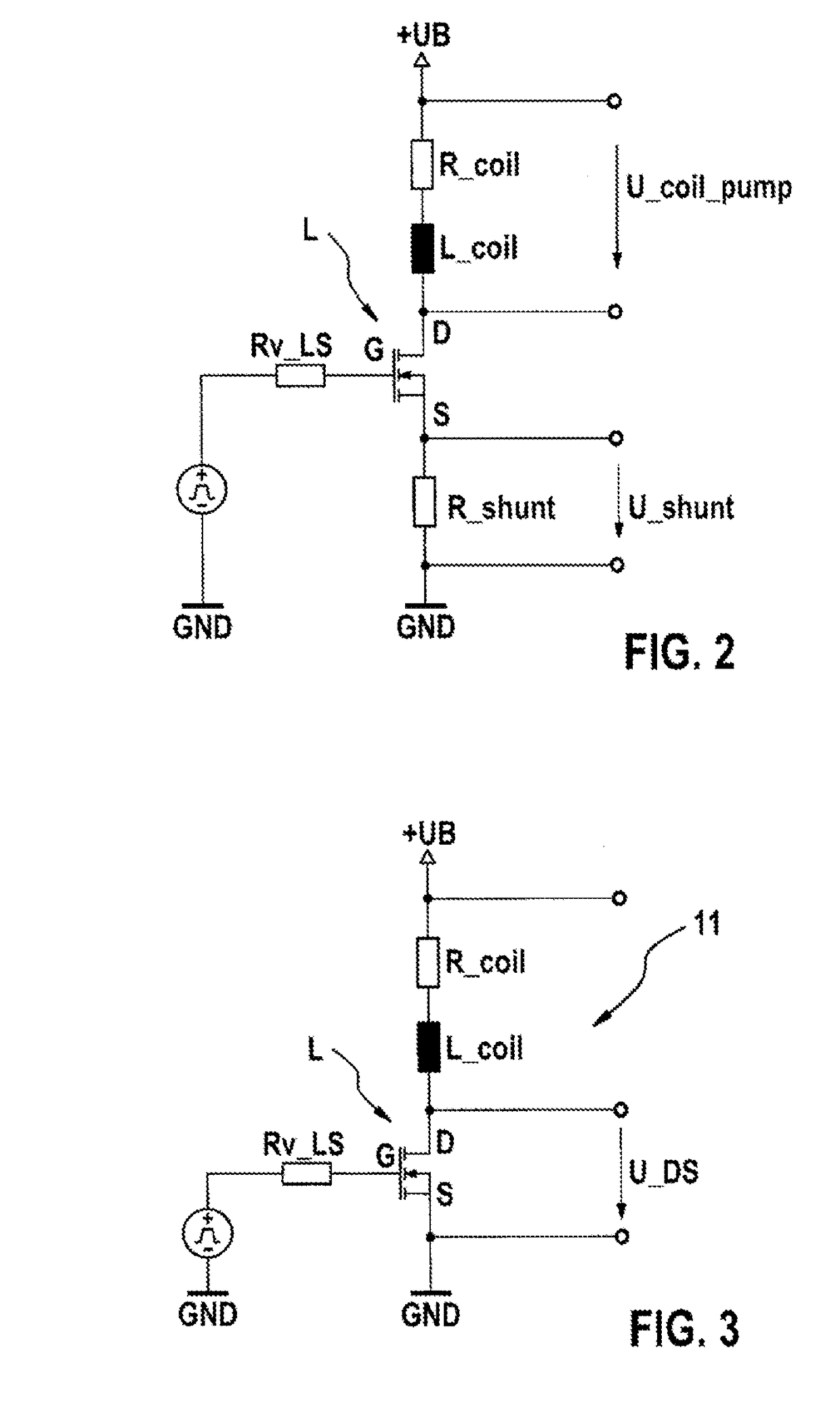
[0039]FIG. 3 shows a circuit diagram of an actuation device, as an element of the invention. This element of the invention is of independent significance. The applicant reserves the option to file a separate application in respect of this subject matter. The actuation device represented can form part of a more extensive unit. Between a supply voltage potential +UB and a ground potential GND, a coil of an electromagnet of a piston pump and a semiconductor switch LS are connected in series. The semiconductor switch LS is configured as a n-channel MOSFET transistor. Alternatively, the semiconductor switch LS can also be configured as a p-channel MOSFET transistor. A source terminal S of the transistor is connected to the ground potential GND. A drain terminal D is connected to one terminal of the coil. The gate terminal G is connected to an actuation potential via a series resistor Rv_LS. A voltage drop U_DS can be tapped-off between the drain D and the source S. The voltage drop can b...


PUM


Abstract

The invention relates to a method for operating a piston pump (10) which is driven by means of a coil (1) of an electromagnet. A piston (2) of the piston pump (10) can be moved in a cylinder (3) for pumping purposes by means of the electromagnet. A voltage (U) is applied to the coil (1) during a switch-on period such that a current flows through the coil (1) and the piston (2) is accelerated, said voltage being applied by means of an actuation device (11). A time curve of an electric state variable (I, U) of the coil (1) is qualitatively detected, and the curve or a curve derived therefrom is analyzed in order to detect an impact of the piston (2) against a stop. The invention further relates to an actuation device and a piston pump.

Description

BACKGROUND OF THE INVENTION[0001]The present invention relates to a method for operating a piston pump, which is driven by means of a coil of an electromagnet, wherein, by means of the electromagnet, a piston of the piston pump is moveable in a cylinder for the execution of a pump action, wherein, during a switch-in time, a voltage is applied to the coil, such that a current flows in the coil and the piston is accelerated, wherein the voltage is applied by means of an actuation device. The invention further relates to an actuation device for a piston pump for the conveyance of a fluid, specifically a fuel, having a cylinder, a piston and an electromagnet with a coil for the movement of the piston in the cylinder. The invention moreover relates to a piston pump.[0002]Piston pumps are known from the prior art which are driveable by means of the coil of an electromagnet. These can be employed, for example, as fuel pumps. For exemplary purposes, one embodiment of a pump of this type as ...

Claims


Application Information

Patent Timeline
IPC IPC(8): F04B49/06F04B17/04F04B19/22
CPCF04B49/06F04B19/22F04B17/04F04B53/14F04B53/16F02D41/3082F02D41/20F02D41/2464F02D2041/2055F02D2041/2051F02D2041/2058F02D2041/2037F04B17/044F04B35/045F04B49/065F04B2201/0201F04B2203/0401F04B2203/0402F04B49/12F04B17/048F04B17/042F04B2201/0206F04B2203/0403F04B2203/0404
Inventor KRUSCH, ANDREAGUTSCHER, ANDREASFLO, SIAMENDALLGEIER, THORSTENMAEURER, WALTER
Owner ROBERT BOSCH GMBH
Why Eureka
Try Eureka