Fuse with separating element

Active Publication Date: 2016-06-02
ROBERT BOSCH GMBH
View PDF7 Cites 2 Cited by
  • Summary
  • Abstract
  • Description
  • Claims
  • Application Information

AI Technical Summary

Benefits of technology

[0009]The fuse according to the invention includes a fusible element with a first portion, with a second portion, and with a connecting portion which connects the first portion to the second portion. The fuse further includes a separating element which has been configured to prevent an arc between the first portion and the second portion. The first portion of the fusible element extends on a first side of the separating element, the second portion of the fusible element exten

Problems solved by technology

For higher currents, fuses are built in, because con

Method used


Image

  • Fuse with separating element
  • Fuse with separating element
  • Fuse with separating element

Examples


Embodiment Construction

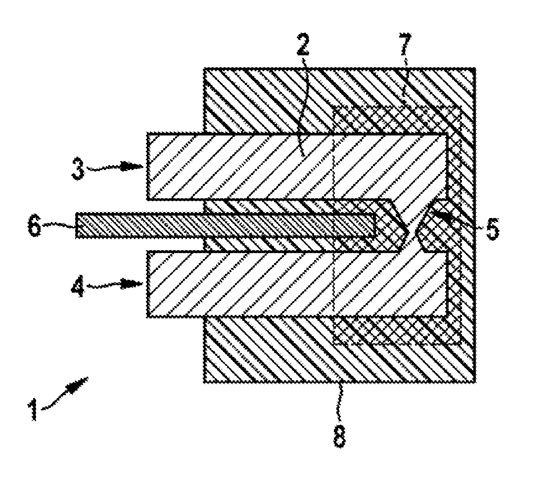
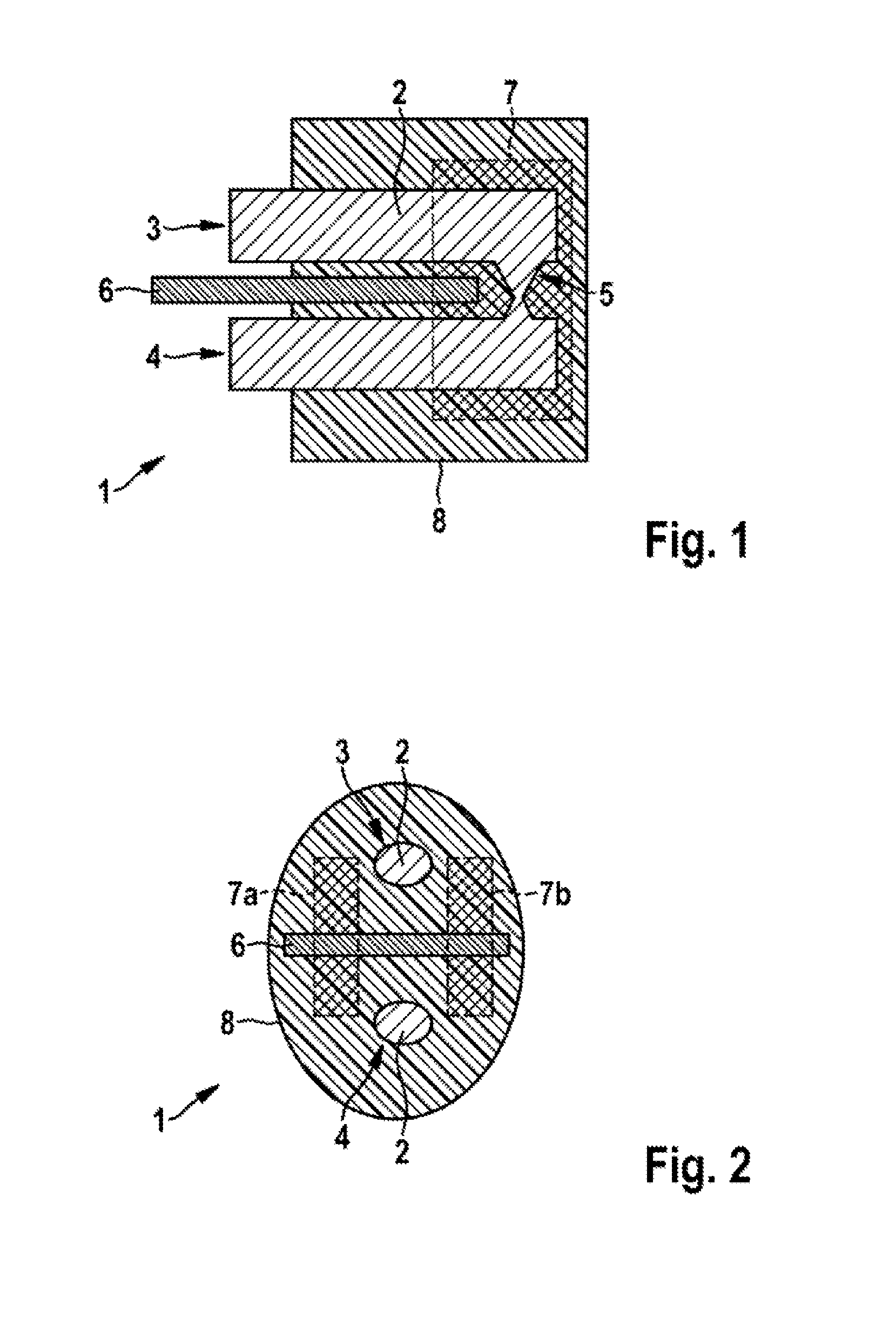
[0022]FIG. 1 shows a schematic view of a cross section through a fuse 1 according to an embodiment of the invention. The fuse 1 includes a fusible element 2 with a first portion 3, with a second portion 4, and with a connecting portion 5. The material of the fusible element has been chosen in such a way that the latter is both electrically conductive and, in the event of high currents, is heated up in such a manner that its melting-point is exceeded. In the embodiment shown here, the fusible element 2 consists of copper.

[0023]The fuse further includes a separating element 6 which has been configured to prevent an arc between the first portion 3 and the second portion 4. An arc may arise, in particular, in the case of a short circuit, and is able to bridge an air gap in the fusible element 2. The separating element 6 therefore consists of ceramic, in order to offer a high insulation resistance and a high thermal resistance.

[0024]The connecting portion 5 and a part of the first and se...


PUM


Abstract

The invention relates to a safety device (1), comprising: a fusible member (2) having a first segment (3), a second segment (4), and a connecting segment (5), which connects the first segment (3) to the second segment (4). The safety device (1) further comprises a separation element (6), configured to suppress a light arc between the first segment (3) and the second segment (4). The first segment (3) of the fusible member (2) extends along a first side of the separation element (6), the second segment (4) of the fusible member (2) extends along a second side of the separation element (6) located opposite the first side, and the connecting segment (5) of the fusible member (2) extends along a third side of the separation element. It is thus achieved that a light arc between the first segment (3) and the second segment (4) of the fusible member (2) cannot exist even if the spatial distance between the first and the second segment (3, 4) of the fusible member (2) is so minimal that it allows a skipping of a light arc.

Description

BACKGROUND OF THE INVENTION[0001]The present invention relates to a fuse with a separating element, in particular to a melting fuse for a vehicle battery.[0002]In high-voltage vehicle batteries, high-voltage contactors are conventionally employed at the external vehicle terminals for the purpose of cutting out excess currents (up to about 1000-2000 A). For higher currents, fuses are built in, because contactors are no longer able to isolate such currents. Located in these fuses, depending on the type, is a fusible element (frequently made of copper) with cross-sectionally constricted portions. These cross-sectionally constricted portions or constrictions melt in the event of short-circuit currents. The higher the current or voltage, the longer an arc is able to remain in existence until it dies out. Fuses with several constrictions are therefore used for high voltages (currently about 450 V) and currents (currently about 8 kA). In this way, at each constriction a clearance arises wh...

Claims


Application Information

Patent Timeline
IPC IPC(8): H01H85/38
CPCH01H2085/386H01H85/38H01H85/0452H01H2085/381H01H2085/383
Inventor ZIEGLER, STEFANGALAMB, GERGELY
Owner ROBERT BOSCH GMBH
Why Eureka
Try Eureka