Low jitter pulse output for power meter

a power meter and low jitter technology, applied in the direction of power supply for data processing, power measurement by digital technique, instruments, etc., can solve the problems of high production cost, low output throughput, and long active energy calibration time,

Inactive Publication Date: 2018-10-23
NXP USA INC
View PDF7 Cites 0 Cited by
  • Summary
  • Abstract
  • Description
  • Claims
  • Application Information

AI Technical Summary

Problems solved by technology

As a consequence the active energy calibration may take longer.
The longer the calibration time, the higher the cost of the production and the lower the production throughput.
These pulse output requirements can be accomplished using a dedicated high-resolution (>=27-bit) pulse output hardware (ASIC) which is an expensive solution.
It allows pulse output generation in a high dynamic range, but a relative long time is required for pulse averaging to eliminate the pulse output jitter.
The longer the testing of the power meter 1, the higher its manufacturing costs and the lower the factory production bandwidth.

Method used


Image

  • Low jitter pulse output for power meter
  • Low jitter pulse output for power meter
  • Low jitter pulse output for power meter

Examples


Embodiment Construction

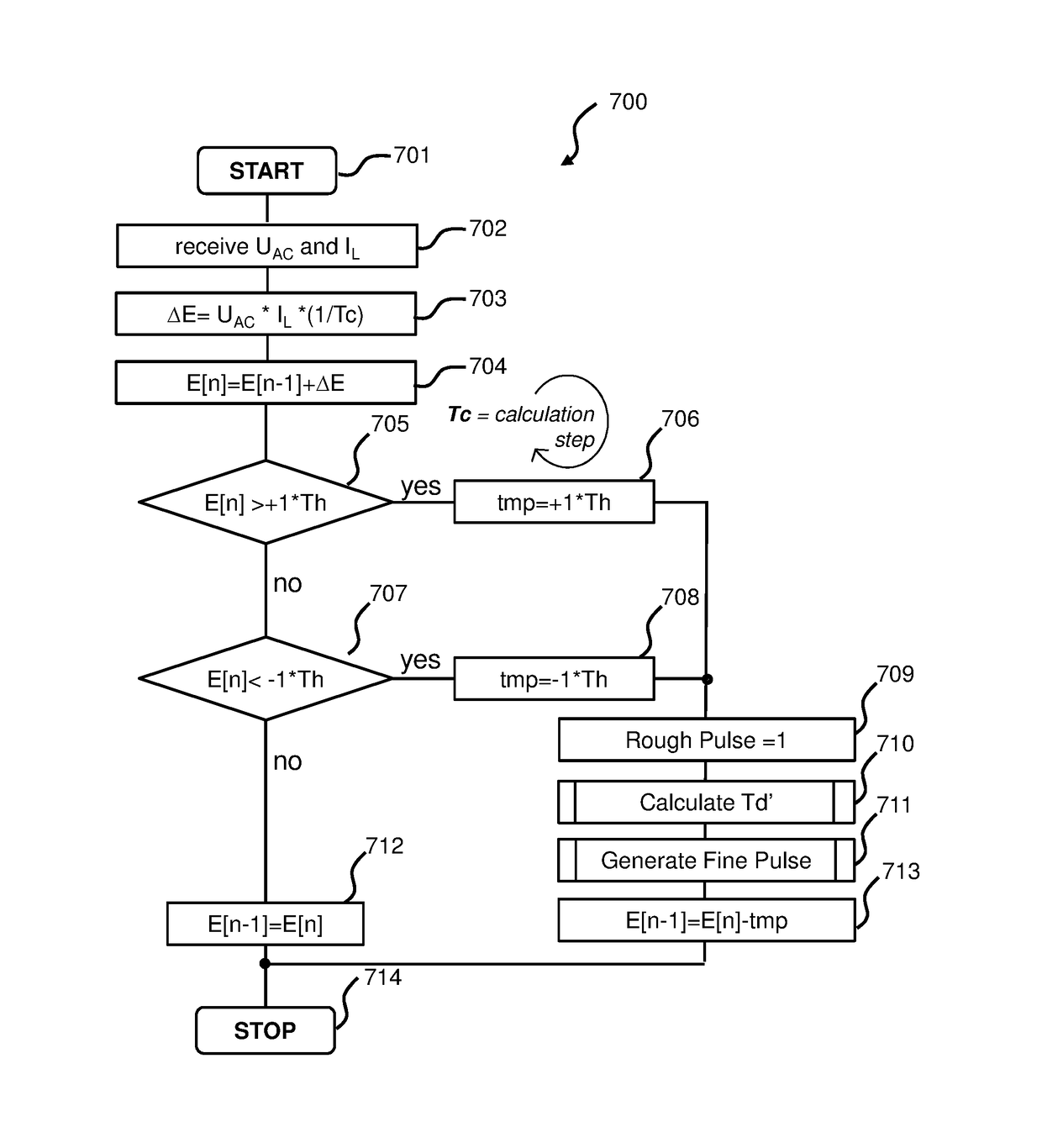
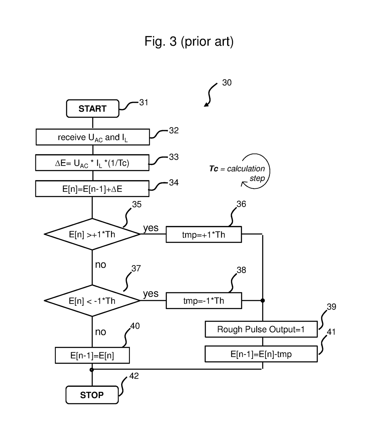
[0035]A new pulse generation technique has been developed to overcome power meter test time issue. In an embodiment the high dynamic range pulse output is achieved by a software algorithm and a simple timer available on most of MCUs—these two elements enable the building of a low jitter pulse output system.

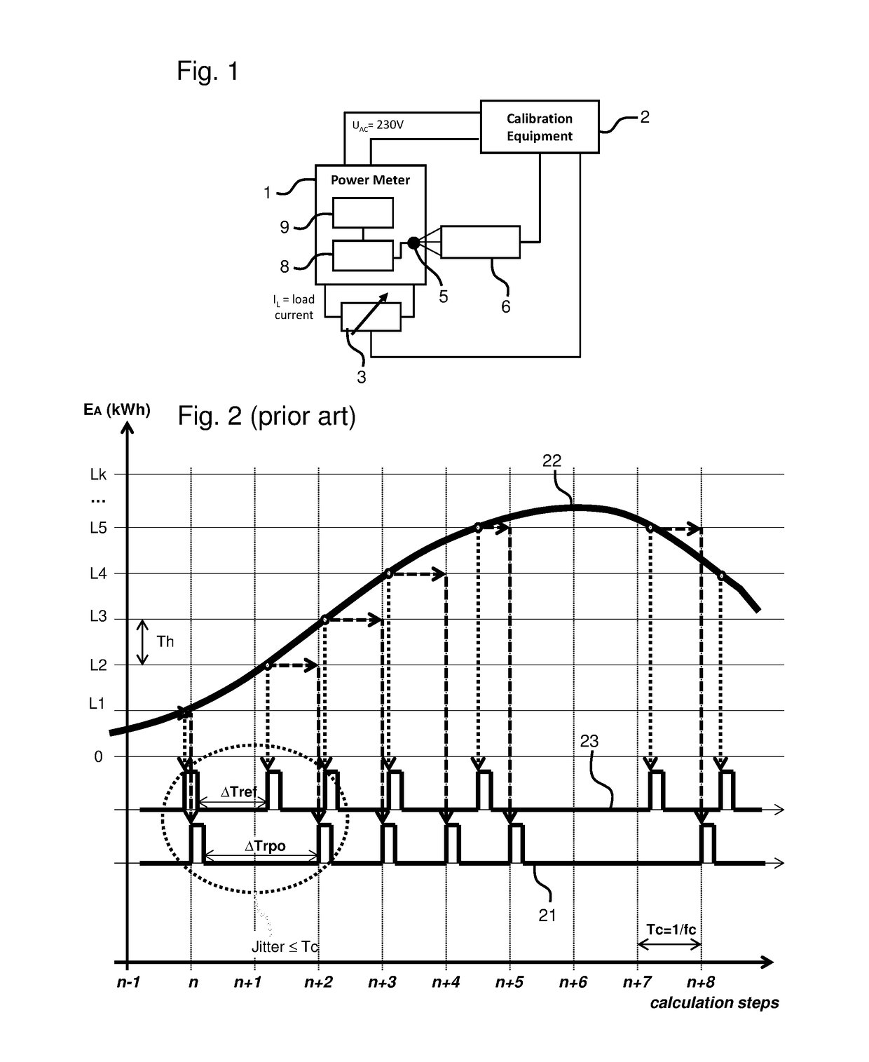
[0036]FIG. 4 shows a graph illustrating a pulse generation method according to an embodiment. A line 50 indicates the instantaneous active energy consumption EA (t) which is controlled by the calibration equipment 2 in a known way. For a given impulse number and energy consumption the calibration equipment 2 generates a “Reference Pulse Output” signal 51.

[0037]At discrete time intervals [n, n+1, . . . ] the software updates active energy counter and whenever updated counter value crosses an active energy level Lk with k=0, 1, 2, . . . , the software also initializes Timer to generate “Fine Pulse Output” signal 52 with a relative delay Td′.

[0038]In FIG. 4ΔTref is referring to the t...


PUM


Abstract

There is provided an energy consumption meter device comprising including a processor arranged to receive input data from the sampling unit. The processor calculates at a calculation step [n] an energy contribution value using ΔE using a sampled voltage value and a sampled current value. The processor will calculate an energy value E[n] using a reminder value which was calculated at a previous calculation step [n−1]. The processor will then calculate a relative delay Td′ using the threshold value, the reminder value and the energy value, and generate an output pulse at an output time tpulse which is delayed for the relative delay Td′ with respect to the calculation time step[n]. By delaying the output pulse with a value which is a closest proximity of Td, the cycle-by-cycle jitter is less or equal to the clock frequency of the timer tclk.

Description

FIELD OF THE INVENTION[0001]This invention relates to an energy consumption meter device. It also relates to a method of generating a pulse, and to a computer program product.BACKGROUND OF THE INVENTION[0002]Power meters are used to measure consumption of electrical energy in households, companies or industry. Most power meters generate pulses on a so-called active energy kWh-LED. Each generated pulse relates to a predefined energy amount which is consumed by the load. The number of pulses generated per kWh is referred to as the pulse number “imp” which is typically between 1,000 and 100,000.[0003]Before selling the power meters, manufacturers perform power meter calibration. FIG. 1 shows a possible configuration for a power meter calibration and testing of a power meter 1. A calibration equipment 2 supplies power with an alternating voltage UAC. It also controls a load current IL using an adjustable load 3 connected to the power meter 1. The power meter 1 measures the load current ...

Claims


Application Information

Patent Timeline
Patent Type & Authority Patents(United States)
IPC IPC(8): G01R21/127G01R21/133G06F1/26G01R35/04G01R22/06
CPCG01R21/127G01R21/133G01R22/06G06F1/26G01R35/04
Inventor MIENKINA, MARTINKOZUB, RADOMIRSLOSARCIK, LUDEKVACULIK, LUKAS
Owner NXP USA INC
Why Eureka
Try Eureka