Duty cycle correction circuit and delay locked loop having the same

a duty cycle correction and delay technology, applied in the field of semiconductor circuits, can solve the problems of deterioration of device capability, time delay generated by internal circuits, frequent deviation of duty cycle of clocks, etc., and achieve the effect of reducing power consumption

Inactive Publication Date: 2005-02-22
CONVERSANT INTPROP MANAGEMENT INC
View PDF13 Cites 105 Cited by
  • Summary
  • Abstract
  • Description
  • Claims
  • Application Information

AI Technical Summary

Benefits of technology

It is, therefore, an object of the present invention to provide a duty cycle correction circuit (DCC) and a delay locked loop (DLL) including the same in order to reduce a power consumption.

Problems solved by technology

When an external clock, which is externally inputted, is used in an internal circuit as an internal clock, a time delay is generated by the internal circuit.
Also, as an operation speed of a device is increased, a duty cycle of the clock is frequently strayed because of a clock distortion.
As a result, an operation fail of the DLL occurs easily and a deterioration of a device capability is induced.
In addition, the clock duty cycle of the DLL circuit may be distorted.
However, the conventional DCC circuit has some drawbacks.
As shown in FIG. 2, the DCC circuit is an analog type and thereby, consuming much power.
Furthermore, the DCC circuits should be disposed before and behind the delay line of the delay line and thereby, occupying too much chip area.

Method used


Image

  • Duty cycle correction circuit and delay locked loop having the same
  • Duty cycle correction circuit and delay locked loop having the same
  • Duty cycle correction circuit and delay locked loop having the same

Examples


Embodiment Construction

Hereinafter, an inventive a duty cycle correction circuit (DCC) and a delay locked loop (DLL) including the same will be described in detail referring to the accompanying drawings.

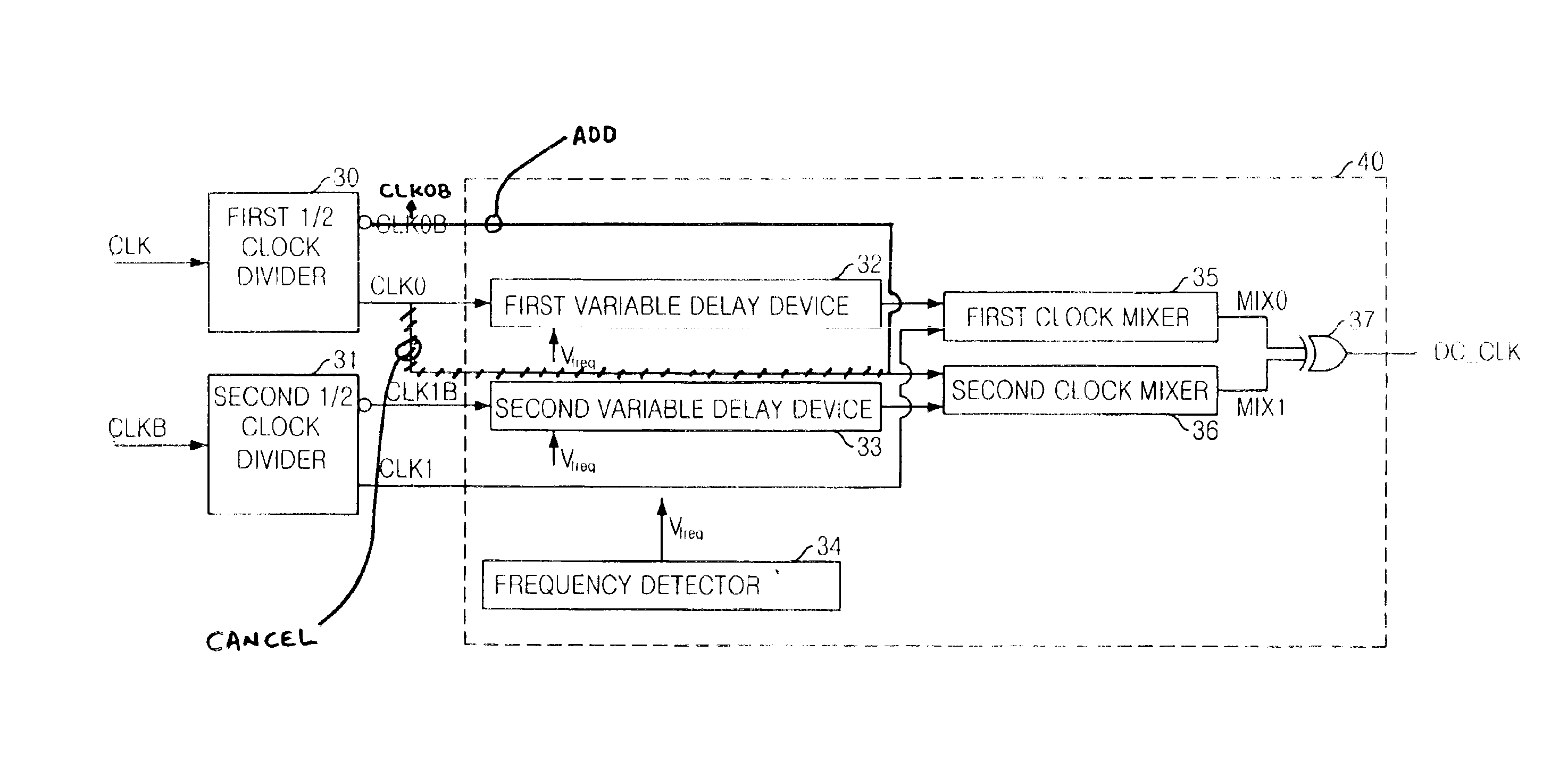
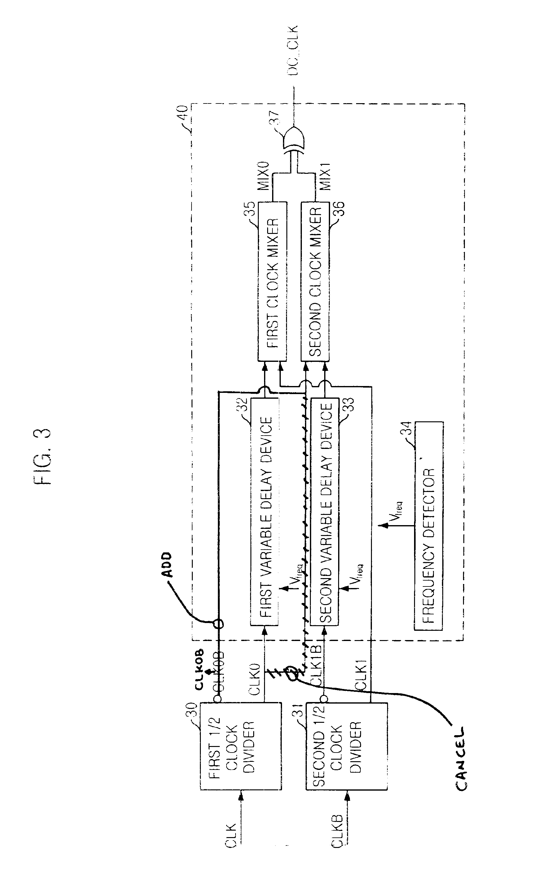
FIG. 3 is a block diagram showing a DCC circuit in accordance with a preferred embodiment of the present invention.

Referring to FIG. 3, the DCC circuit includes: a first ½clock divider 30 for generating ordinary divided clocks (CLK0 and CLK0B) which are obtained by dividing an ordinary input clock (CLK) by 2; a second ½clock divider 31 for generating clocks (CLK1 and CLK1B) which are obtained by dividing a sub ordinary input clock (CLKB) by 2; and a DCC core 40 for generating a duty cycle corrected clock (DC_CLK) having a corrected duty cycle, by correcting the duty cycle of outputs from the first and second clock divider 30.

The DCC core 40 includes: a frequency detector 34 for generating a voltage signal (Vfreq) varied in proportion to a wave frequency; a first variable delay device 32 for delaying an ord...


PUM


Abstract

A duty cycle correction (DCC) circuit including first and second clock dividers for dividing ordinary and sub-input clocks. Optional first and second variable delay devices delay the divided clocks. First and second mixers mix an optionally delayed ordinary divided clock and sub-ordinary divided clock, or an ordinary divided clock and an optionally delayed sub-ordinary divided clock. A logic combination device is included to produce a clock at the same frequency as the ordinary and sub-input clocks, with a corrected duty cycle.

Description

FIELD OF THE INVENTIONThe present invention relates to a semiconductor circuit, and more particularly, to a duty cycle correction circuit (DCC) and a delay locked loop (DLL) having the same.DESCRIPTION OF RELATED ARTSUsually, a clock is used as a reference for adjusting operation timing. The clock is also used for guaranteeing much more rapid operation without any error. When an external clock, which is externally inputted, is used in an internal circuit as an internal clock, a time delay is generated by the internal circuit. The DLL is used to obtain a same phase of the internal clock and the external clock by compensating the time delay between the external clock and internal clock.Also, the DLL is less affected by a noise than a conventional phase locked loop (PLL). Consequently, the DLL is commonly used for a double data rate synchronous DRAM (DDR SDRAM) and a synchronous semiconductor memory. Also, the DLL is classified by methods of controlling the delay, and recently, an anal...

Claims


Application Information

Patent Timeline
Patent Type & Authority Patents(United States)
IPC IPC(8): H03L7/081H03L7/08H03L7/089H03K5/156
CPCH03K5/1565H03L7/0812H03L7/0805H03L7/0891H03L7/0816H03L7/08
Inventor HONG, SANG-HOONKIM, SE-JUNKOOK, JEONG-HOON
Owner CONVERSANT INTPROP MANAGEMENT INC
Why Eureka
Try Eureka