
Aircraft comprising a plurality of antenna units
a technology of antenna units and aircraft, applied in the direction of antennas, satellite transmit diversity, transmission, etc., can solve the problems of time-consuming, limited, expensive, etc., and achieve the effect of reducing the amount of additional cabling required
- Summary
- Abstract
- Description
- Claims
- Application Information
AI Technical Summary
Benefits of technology
Problems solved by technology
Method used
Image

Examples
first embodiment
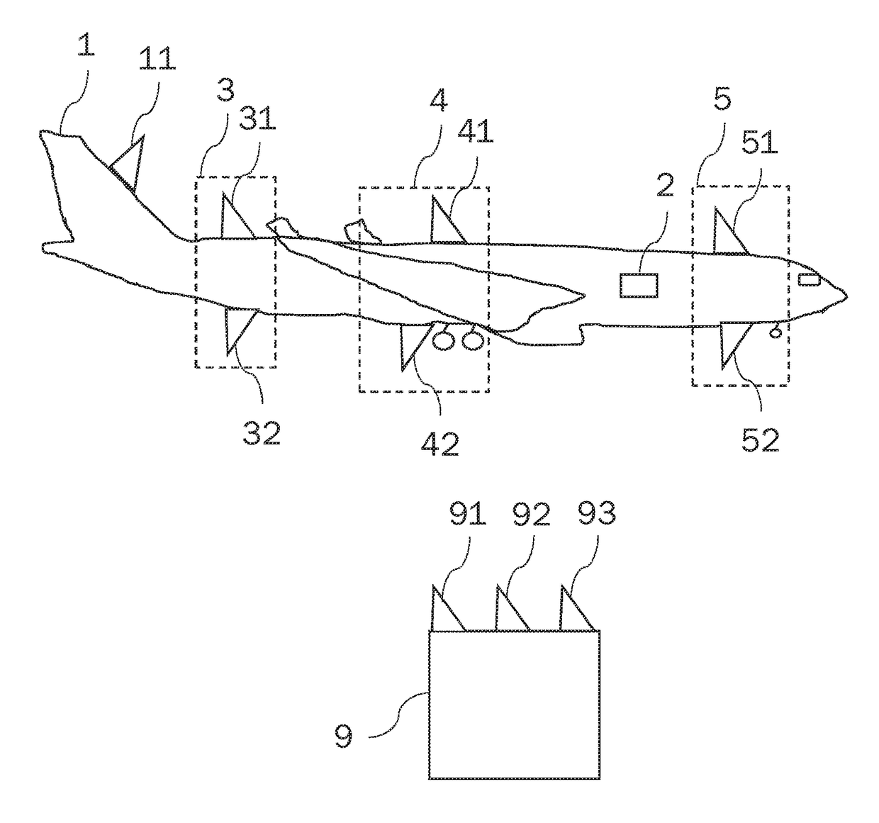
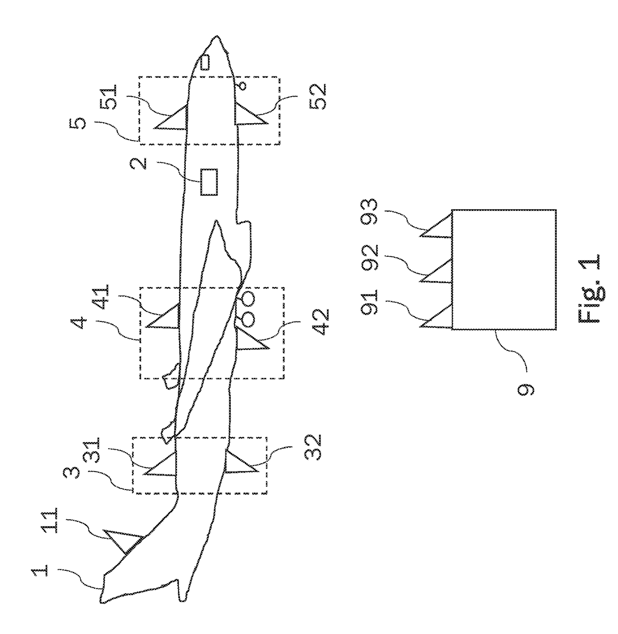
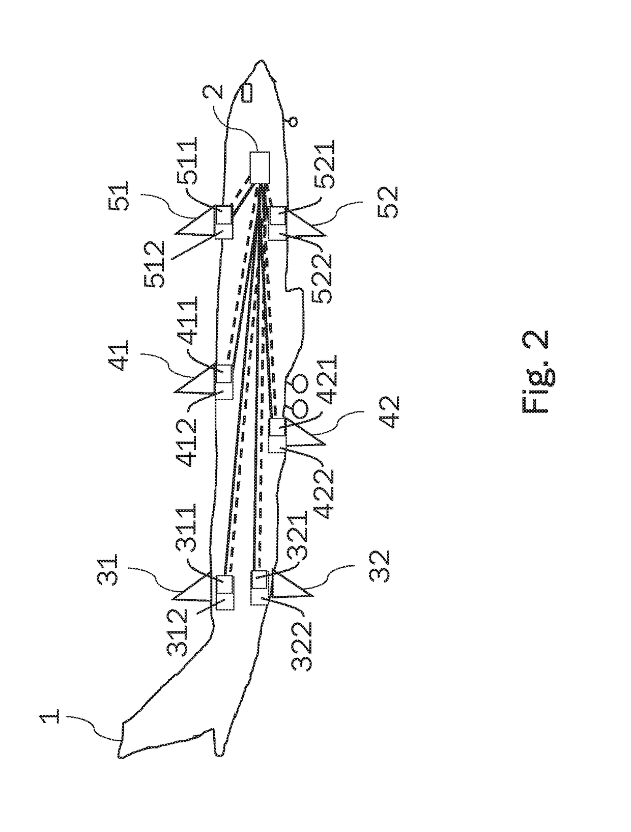
[0039]FIG. 2 and FIG. 3 show a possible first embodiment in which the central control unit 2 is electrically connected to the antenna elements 31, 32, 41, 42, 51, 52 by means of communication modules 311, 321, 411, 421, 511, 521. FIG. 3 does not show the two communication modules 511, 521 and the associated antenna elements 51, 52. The communication modules 311, 321, 411, 421, 511, 521 are connected to the control unit 2 by means of a data bus, which is indicated by continuous lines. Inter alia, the user data received or transmitted by the antenna elements 31, 32, 41, 42, 51, 52 are transmitted via the data bus. In the illustrated example, the communication modules 311, 321, 411, 421, 511, 521 are implemented by means of software-defined radio (SDR) platforms which are connected to the central control unit 2 by means of SDR links. The SDR links are indicated in FIG. 2 and FIG. 3 by dashed lines and ensure coherent clocking of the distributed SDR platforms. As shown in FIG. 2, the co...
second embodiment
[0042]The central SDR cluster 21 makes is possible to arrange the SDR platforms 311, 321, 411, 421, 511, 521 in the aircraft 1 in a compact and efficient manner The coherent links between the individual SDR platforms 311, 321, 411, 421, 511, 521 can be produced quickly and simply. In particular, in the second embodiment, there is no need for SDR links between the central control unit 2 and the SDR cluster 21, but rather only SDR links within the SDR cluster 21 are required, and this is indicated by double-headed arrows in FIG. 5.
[0043]FIG. 6 shows another possible application scenario in a helicopter. In this case, three antenna units 6, 7, 8 are actuated by means of a central control unit 2 via a central SDR cluster 21 in order to form a multi-antenna system and allow MIMO data transmission to other communication participants by means of the antenna units 6, 7, 8. In the example shown in FIG. 6, the antenna elements 6, 7, 8 are connected to the SDR cluster 21 by means of the transm...
PUM
 Abstract
Description
Claims
Application Information