Multi-electrode mapping catheter

a multi-electrode, catheter technology, applied in the field of cardiac mapping, can solve the problems of limited capability of endocardial mapping catheters, difficult to accurately map the heart, stroke, etc., and achieve the effect of reducing the rigidity of the catheter shaft, reducing manufacturing costs, and inherent resilience to expansion

Active Publication Date: 2018-10-30
X RHYTHM LLC
View PDF38 Cites 1 Cited by
  • Summary
  • Abstract
  • Description
  • Claims
  • Application Information

AI Technical Summary

Benefits of technology

[0024]In one particular aspect, the present invention is directed to a whole-cardiac-chamber, high-density, three-dimensional multi-electrode catheter adapted for cardiac endocardial contact mapping. The catheter utilizes an array of multiple electrodes arranged in a known spatial configuration that are placed on a flexible substrate to form an expandable basket (also referred to as a “frame”) designed to conform to the target heart chamber so that the multiple electrodes come into intimate contact with the heart wall while accommodating wall motion of the beating heart. A placement of a large number of electrodes on the expandable basket makes it possible to perform endocardial mapping more accurately and rapidly and which make possible simultaneous measurements of an entire chamber in the heart by providing electrode coverage over the entire area. The use of a large number of electrodes over the target area provides the medical professional with a high resolution map of the heart chamber.
[0034]In one particular aspect, the multi-electrode catheter can be made with fourteen individual splines with fifteen electrodes placed on each spline for a total of two-hundred and ten electrodes. The use of the flex circuit on the catheter made in accordance with the present invention allows the mapping catheter to be placed in a low profile contracted configuration, allowing it to be delivered through a standard 8.5Fr sheath into the left atrium. It should, however, be appreciated that the profile of the mapping catheter can be greater than 8.5 Fr in order to accommodate certain ablation catheters. Upon exiting the sheath, the expandable basket has inherent resilience to expand and conform to the chamber of the heart it is placed because of the use of a new design construct. The basket can be adapted to match the human atrium and will be offered in 45 mm, 55 mm, and 65 mm diameters (expanded). It can be made of an all polymer composite, eliminating the need for a nitinol support. Alternatively, the expandable basket can be made with both polymer and nitinol components. This construction provides for optimal electrode to endocardial wall contact, a very important performance parameter needed to obtain high density and high fidelity electrograms. Alternatively, push / pull wires can be associated with the expandable basket to allow the user to manually change the size (diameter) and shape of the expanded basket, as needed.

Problems solved by technology

Cardiac arrhythmias involve an abnormality in the electrical conduction of the heart and are a leading cause of stroke, heart disease, and sudden cardiac death.
Endocardial mapping catheters have been of limited capability because they only have a few electrodes which makes it difficult to accurately map the heart.
Such a procedure has been found to be time consuming and relatively inaccurate.
However, this improvement does not eliminate the need to maneuver across the endocardial surface to map a heart chamber.
This method, called sequential contact mapping, does not provide a whole chamber map during a single cardiac cycle.
In addition, a user must hold the catheter in position, often with his hand positioned awkwardly, making it difficult and inconvenient for a single operator to use separate mapping and ablation catheters.
Ablation catheters have mapping capability, however, they only offer a few electrodes severely limiting their mapping utility.
However, the use of undersized arrays of electrodes necessitates maneuvering the catheter in stepwise fashion across the entire endocardial wall, stopping at each increment to measure electrograms, then proceeding to the adjacent unmapped region until the whole chamber has been mapped in this manner.
It is not possible to create a whole chamber map in a single beat of the heart using this design.
The regional mapping approach is time consuming.
Moreover, in unstable arrhythmias such as atrial fibrillation, this design is inadequate to guide ablation.
Mapping catheter usually requires a sophisticated steering system to position and maneuver the catheter within the patient's vasculature and heart chamber, adding complexity and cost.
Additionally, the steering apparatus is sometimes located within the lumen of the catheter thereby obstructing the lumen from other uses.
Moreover, the operator will likely need to hold the mapping catheter in position to guide ablation, making it difficult for a single operator to map and ablate using two different devices.
As medical knowledge increases, catheterizations have become more complicated and more exacting.
However, when ablating atrial fibrillation or other complex macro-arrhythmias such as atrial flutter, these devices have significant limitations that result in long procedure times, poor outcomes, and an unacceptably high rate of complications.
Moreover, electrical abnormalities are usually diagnosed by mapping electrical activation paths along the endocardial surfaces of the heart chambers over time.
The stability of the arrhythmia allows for this somewhat cumbersome technique.
Each wire assembly adds unwanted stiffness to the catheter and the individual components can only be reduced in size to practical limits dictated by several factors such as assembly, machining capabilities, and strength requirements.
Assembling individual components into a subassembly as described requires labor-intensive processes escalating the cost to manufacture such a device.
Polyimide is a common substrate material for a flex circuit but is typically thick imparting unwanted stiffness and poor resilience when used in a catheter.
Also, when a flex circuit was used, it was often prone to kinking in the small curvatures required of an expandable array.
Most, importantly, however, was that it was impractically expensive to form flex circuits of sufficient length to use in a catheter.
Soldering individual wires to a flex circuit within the length of the catheter made for complicated and expensive manufacturing techniques.
Multiple interconnections of flex circuits to other flex circuits or other components can increase the noise level along the circuit path, which can decrease the flex circuit's usefulness for detecting very low level electrical cardiac signals.
While flex circuits have yielded some improvements in the circuitry field, flex circuit technology, while suggestive of potential, does not improve upon existing mapping catheter designs.

Method used


Image

  • Multi-electrode mapping catheter
  • Multi-electrode mapping catheter
  • Multi-electrode mapping catheter

Examples


Embodiment Construction

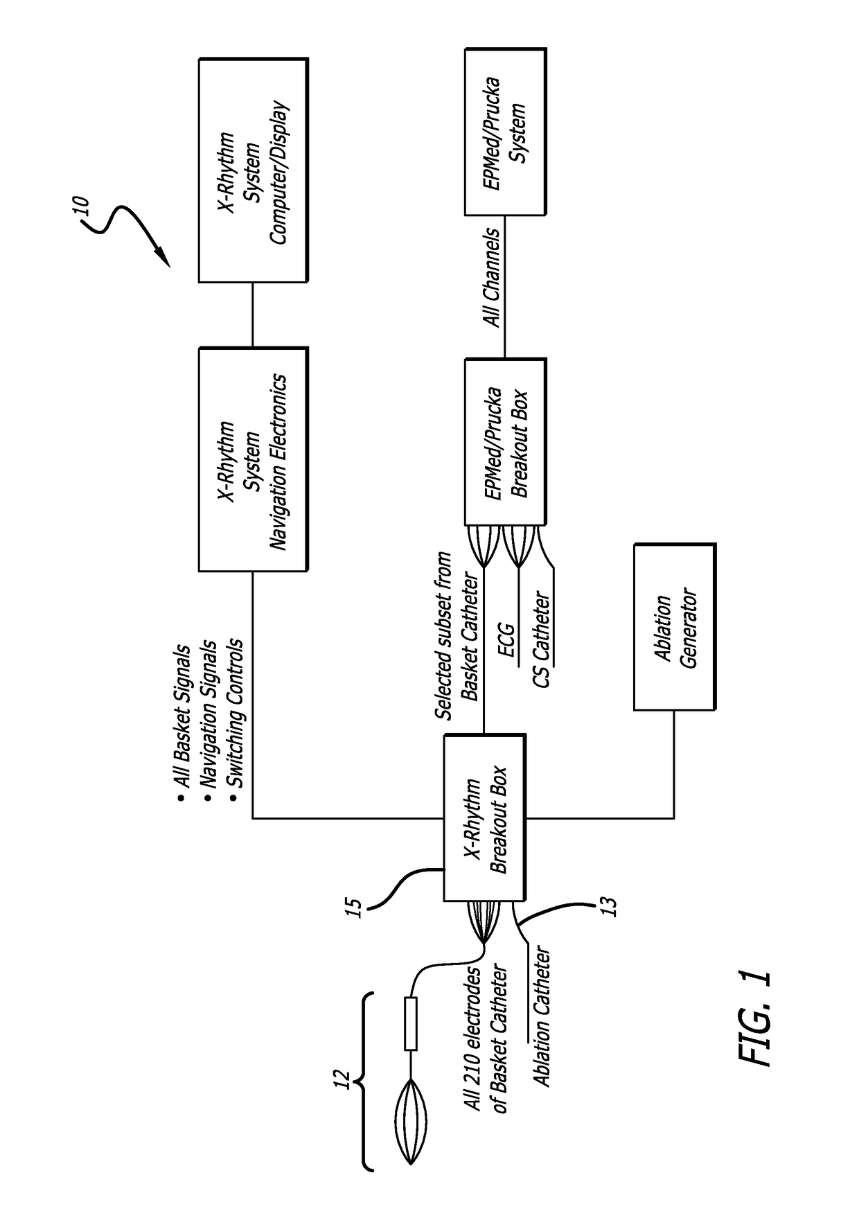
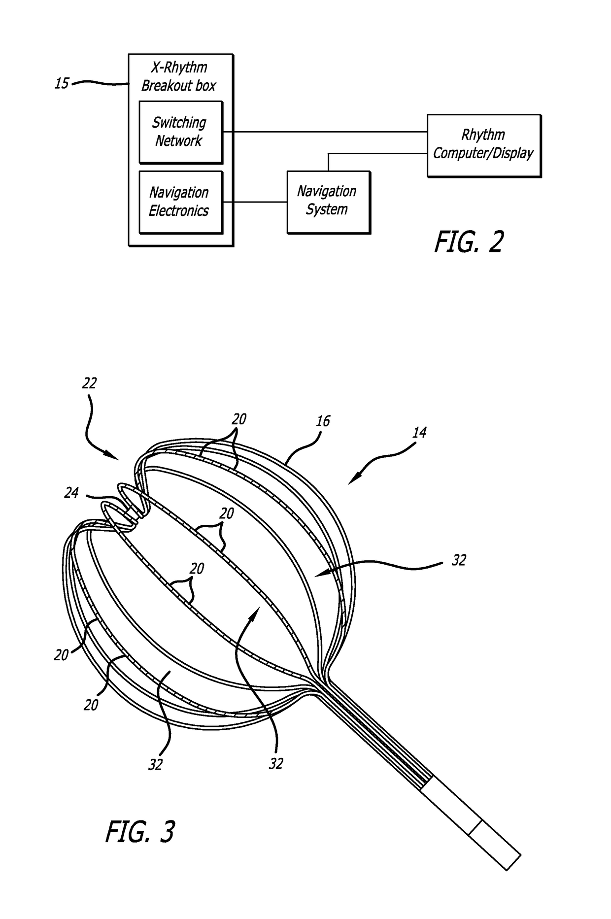
[0061]Turning now in more detail to the drawings in which like reference numerals indicate like or similar elements across the several views, FIGS. 1 and 2 schematically depict a endocardial mapping and ablation system 10 which incorporates a multi-electrode mapping catheter 12 which embodies features of the present invention. The mapping catheter 12 (described in greater detail below) and an ablation catheter 13 are connected to the system through a breakout box 15 (similar to the CIM or catheter input module of the Carto® system or the Nay modules of the NavX™ system). The breakout box serves to route all signals to the main system, as needed, while allowing user selected signals to be forwarded to the EP system, as well as connecting the ablation generator to the ablation catheter 13. The system's mapping function uses the cardiac signals detected from the heart surface via electrodes located on the mapping catheter 12 to create a real time, three dimensional (3D) activation map ...


PUM


Abstract

A multi-electrode mapping catheter for endocardial contact mapping of a heart chamber includes an expandable basket movable between a contracted configuration and a pre-shaped deployed configuration, the expandable basket including a plurality of flexible splines. Each spline includes a flex circuit and an electrode for mapping. A catheter shaft extending from the basket includes a lumen formed therethrough for receiving an ablation catheter for placement within the expandable basket. Each flex circuit includes a conductor that directly connects the proximal end of the catheter shaft to an electrode as a single continuous piece. In another embodiment, a shaft flex circuit extends along the length of the shaft and is electrically connected to a basket flex circuit. The expandable basket maintains the electrodes in direct contact with the wall of the heart while accommodating wall motion of the beating heart during mapping and can continually map while ablating.

Description

CROSS REFERENCES TO RELATED APPLICATIONS[0001]This application claims the benefit of U.S. Provisional Application No. 62 / 050,071, filed Sep. 12, 2014, incorporated herein by reference.FIELD OF THE INVENTION[0002]The invention relates generally to cardiac mapping, and more particularly, to a whole cardiac chamber, high density, multi-electrode mapping catheter adapted for cardiac endocardial contact mapping. At least a portion of the multi-electrode mapping catheter is formed from a flexible substrate. The multi-electrode mapping catheter can be utilized with a mapping system to provide instantaneous whole chamber voltage mapping of a heart chamber while enabling real time electroanatomic mapping utilizing a single heartbeat. The multi-electrode mapping catheter and its associated mapping system can be used with an ablation system to enable real time ablation mapping by depicting fully ablated areas on a graphical display to provide instantaneous feedback of ablation efficiency and t...

Claims


Application Information

Patent Timeline
Patent Type & Authority Patents(United States)
IPC IPC(8): A61B5/00A61B18/14A61B5/042A61M25/06A61M25/00A61B18/00
CPCA61B5/6858A61B5/0422A61B18/1492A61B2018/00839A61B2018/00577A61B2018/00642A61B2018/00357A61B5/287
Inventor JUNG, EUGENEJUNG, ROBERT S.
Owner X RHYTHM LLC
Why Eureka
Try Eureka