
Pressure limiting valve for a cryostat containing a cryogen and a superconducting magnet

a technology of superconducting magnets and quench valves, which is applied in the direction of valve housings, superconducting magnets/coils, container discharge methods, etc., can solve the problems of excessive cryogen gas lifting and venting of the quench valve, rapid boil-off of a large volume of cryogen, etc., and achieves safe air transportation and simple and reliable technique.

Active Publication Date: 2018-10-30
SIEMENS HEALTHCARE LTD
View PDF23 Cites 0 Cited by
  • Summary
  • Abstract
  • Description
  • Claims
  • Application Information

AI Technical Summary

Benefits of technology

[0010]It is therefore an object of the present invention to provide a simple and reliable technique to ensure a safe air transportation of a cryostat containing a cryogen.
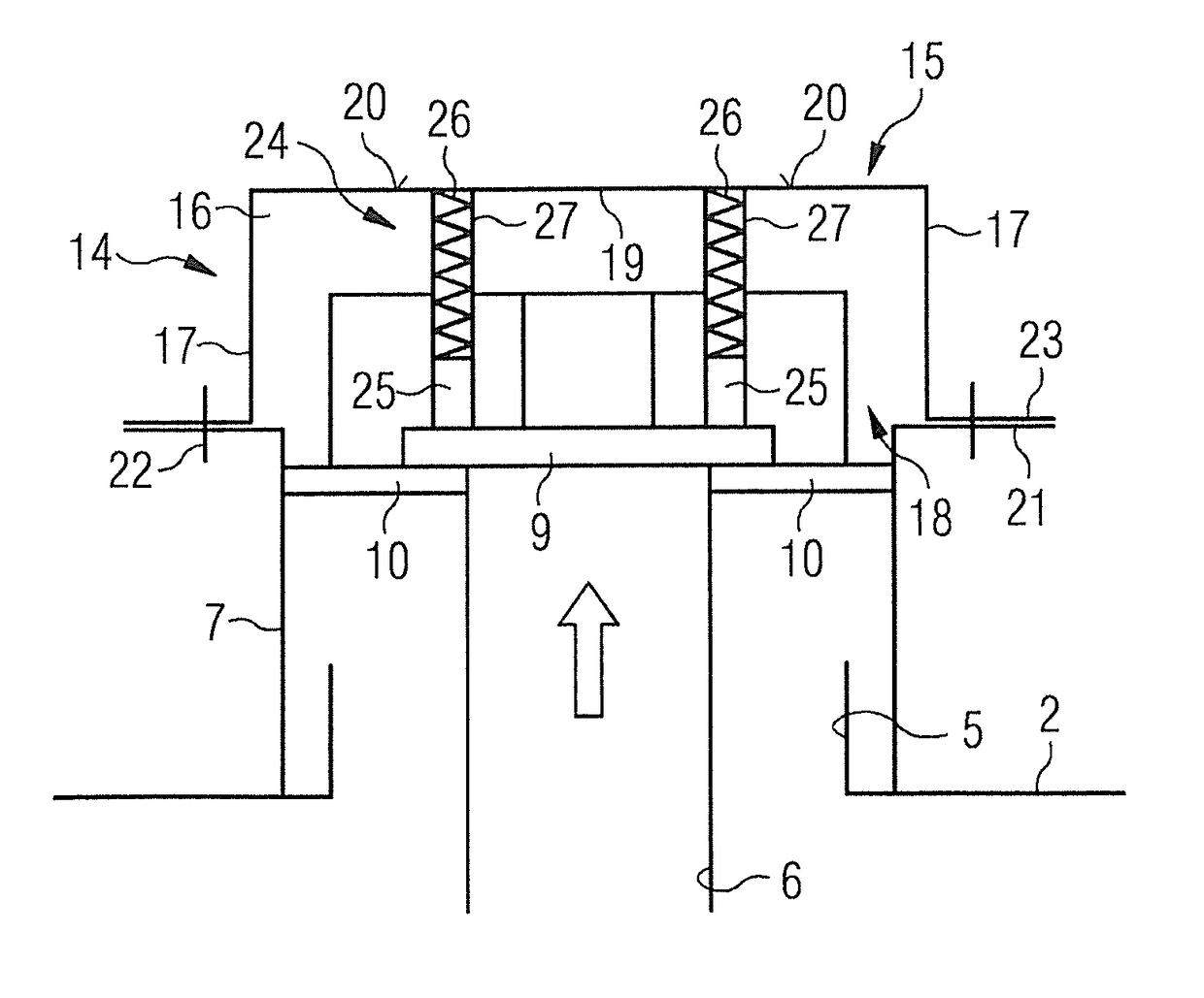
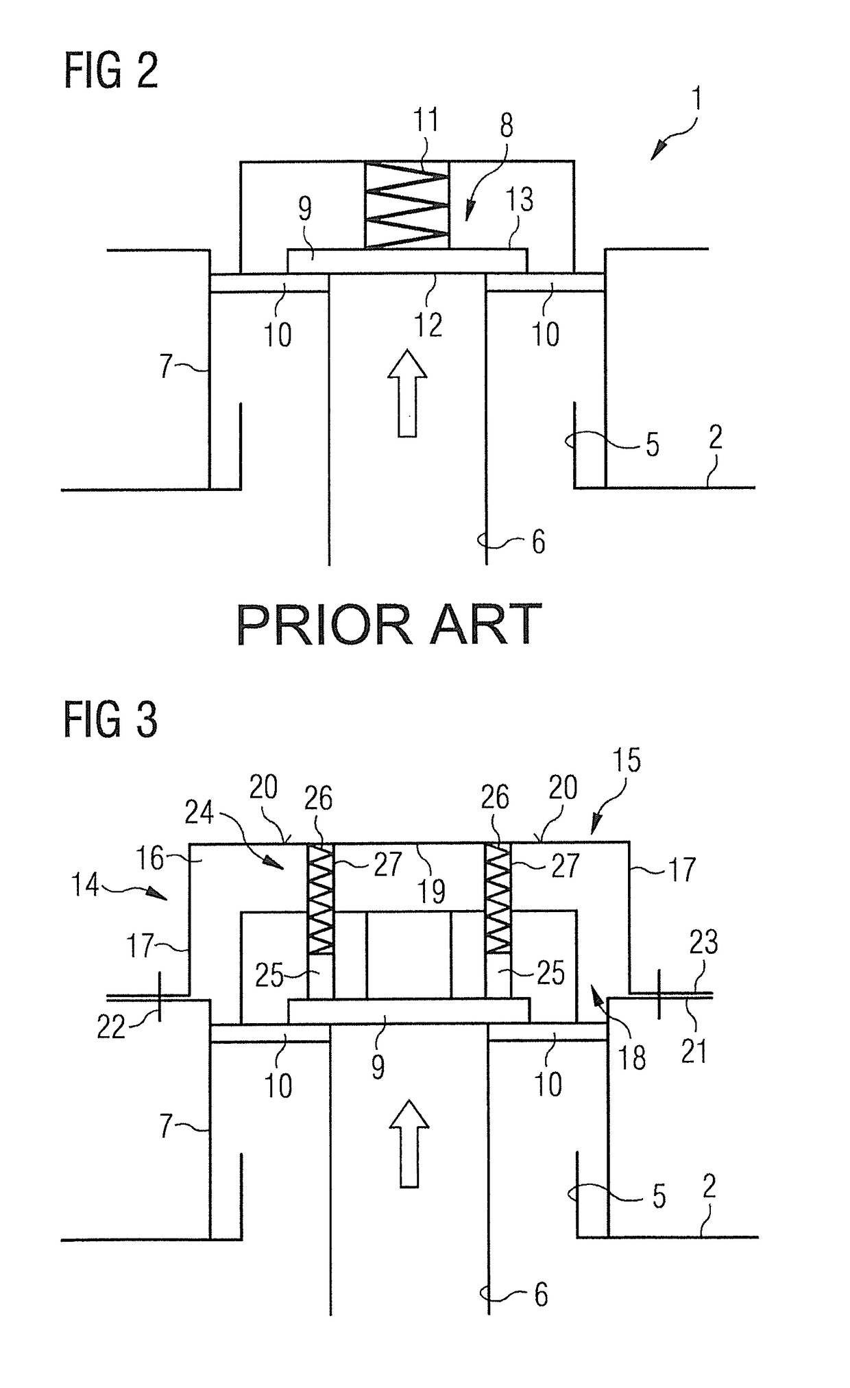
[0011]A core idea of the invention is to enable the existing quench valve of the cryostat to serve as a pressure-relief device during air transportation of the cryostat, in a way that the quench valve remains fully operable. In other words, the operating ability of the quench valve is not restricted. Merely the cracking pressure of the quench valve is temporarily raised for the purpose of air transportation. By this means, a safe air transportation of a cryostat containing a cryogen is achieved in a simple, reliable and very effective way, thereby following safety regulations.

Problems solved by technology

In a superconducting magnet cooled by a liquid cryogen, this typically results in rapid boil-off of a large volume of the cryogen, with gaseous and liquid cryogen being expelled from the cryostat at high speed.
During transportation of an already assembled system, filled with cryogen, no cooling can be provided to the cryogen, which leads to a heat input into the cryostat, leading to a boil-off of cryogen.
However, the change of atmospheric pressure during an air shipment, even in a pressurized compartment, can cause a problem with the relief devices employed.
Therefore, the quench valve would lift and vent excessive cryogen gas.
The whole assembly needs to be leak tight and fully tested, making this an expensive solution.
Furthermore, the assembly is discarded after arrival on operational site.

Method used


Image

  • Pressure limiting valve for a cryostat containing a cryogen and a superconducting magnet
  • Pressure limiting valve for a cryostat containing a cryogen and a superconducting magnet
  • Pressure limiting valve for a cryostat containing a cryogen and a superconducting magnet

Examples


Embodiment Construction

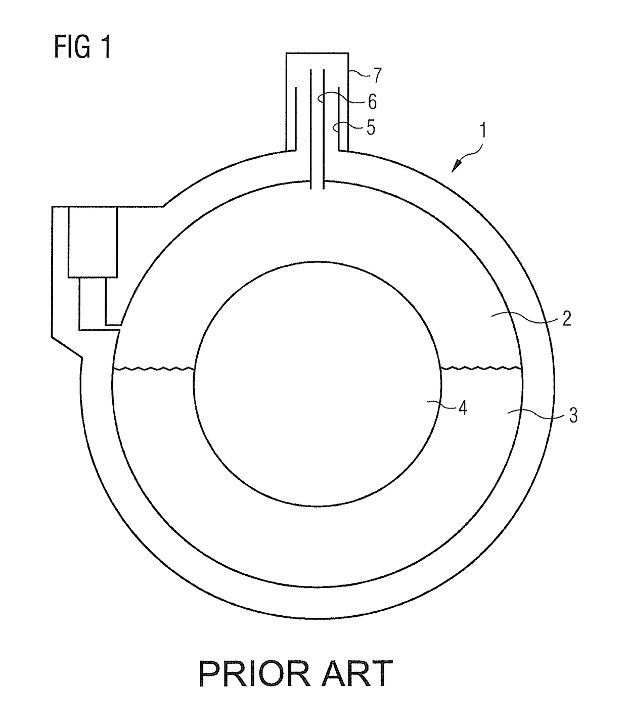
[0016]A cross-section of a superconducting magnet system for use in an MRI system is illustrated in FIG. 1. Superconductive magnet coils (not shown) are provided in a cryogen vessel 2 of a cryostat 1. The coils are immersed in a liquid cryogen 3, e.g. liquid helium. A central bore 4 is provided to accommodate a patient for examination. An access neck 5 with vent tube 6 is provided at the top of the cryostat 1 to allow access to the cryogen vessel 2. For clarity reasons, other parts of the cryostat 1, e.g. the refrigerator for providing active refrigeration to cool the cryogen 3, the outer vacuum chamber, or the thermal radiation shields, are not shown.

[0017]As illustrated in FIG. 2 in more detail, a turret outer assembly 7 encloses upper extremities of the access neck 5, and provides a normal exit path for cryogen gas from cryogen vessel 2. Turret outer assembly 7 is joined to the cryogen vessel 2 in a leak-tight manner and defines an interior volume which is separated from atmosphe...


PUM

PropertyMeasurementUnit
cracking pressureaaaaaaaaaa
pressureaaaaaaaaaa
MRIaaaaaaaaaa

Abstract

An abstract for a quench valve of a cryostat, in particular for use in a magnetic resonance imaging system, is attachable to the quench valve so as to raise the cracking pressure of the quench valve without changing the operability of the quench valve. Such an accessory device is usable to enable the cryostat, containing a cryogen, to be safely transported by air transportation.

Description

BACKGROUND OF THE INVENTION[0001]Field of the Invention[0002]This invention relates to an accessory device for a quench valve of a cryostat, in particular for use in a magnetic resonance imaging (MRI) system. Furthermore, this invention relates to a method of enabling a cryostat containing a cryogen to be safely transported by air transportation.[0003]Description of the Prior Art[0004]Superconducting magnet systems are used for medical diagnosis, for example in magnetic resonance imaging systems. A requirement of an MRI magnet is that it produces a stable, homogeneous, magnetic field. In order to achieve the required stability, it is common to use a superconducting magnet system which operates at very low temperature. The temperature is typically maintained by cooling the superconductor by immersion in a low temperature cryogenic fluid, also known as a cryogen, such as liquid helium.[0005]The superconducting magnet system typically comprises a set of superconductor windings for prod...

Claims


Application Information

Patent Timeline
Patent Type & Authority Patents(United States)
IPC IPC(8): F17C13/04F16K17/04F17C13/00H01F6/02F16K17/08F16K24/04F17C3/00F16K17/18
CPCF16K17/0413F16K17/044F16K17/08F17C13/04H01F6/02F17C13/007F17C2270/02F17C2205/0332F16K27/08F17C3/085
Inventor RETZ, PATRICK WILLIAMTIGWELL, NEIL CHARLES
Owner SIEMENS HEALTHCARE LTD
Learn More