
System and method for measurement of angular orientation of aerospace platforms

a technology for determining the orientation and positioning of the platform, which is applied in the direction of instruments, instruments, instruments for force/torque/work measurement, etc., can solve the problems of affecting the measurement accuracy of the platform, the inability to implement an ahrs or ins with these types of rate gyros, and the accumulation of bias measurement errors. substantial, the effect of affecting the accuracy of the measuremen

Active Publication Date: 2015-05-12
ISRAEL AEROSPACE IND
View PDF13 Cites 3 Cited by
  • Summary
  • Abstract
  • Description
  • Claims
  • Application Information

AI Technical Summary

Benefits of technology

[0014]A need exists for a highly reliable and simple technique to correct errors resulting from the bias drift of roll rate gyro which might be significant in systems of the type utilizing rate gyros having large bias drift rates (e.g. AHRS and INS).
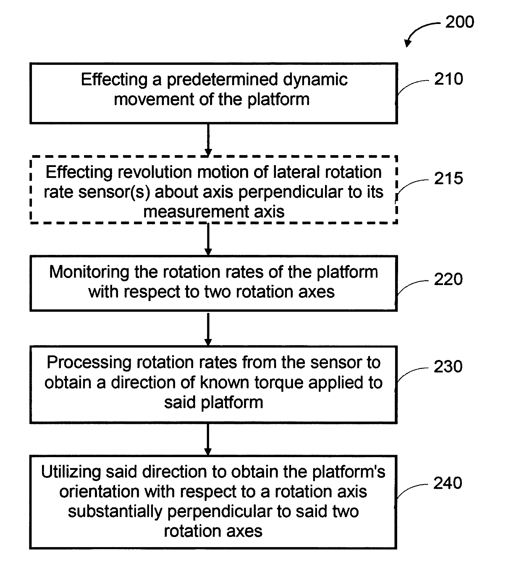
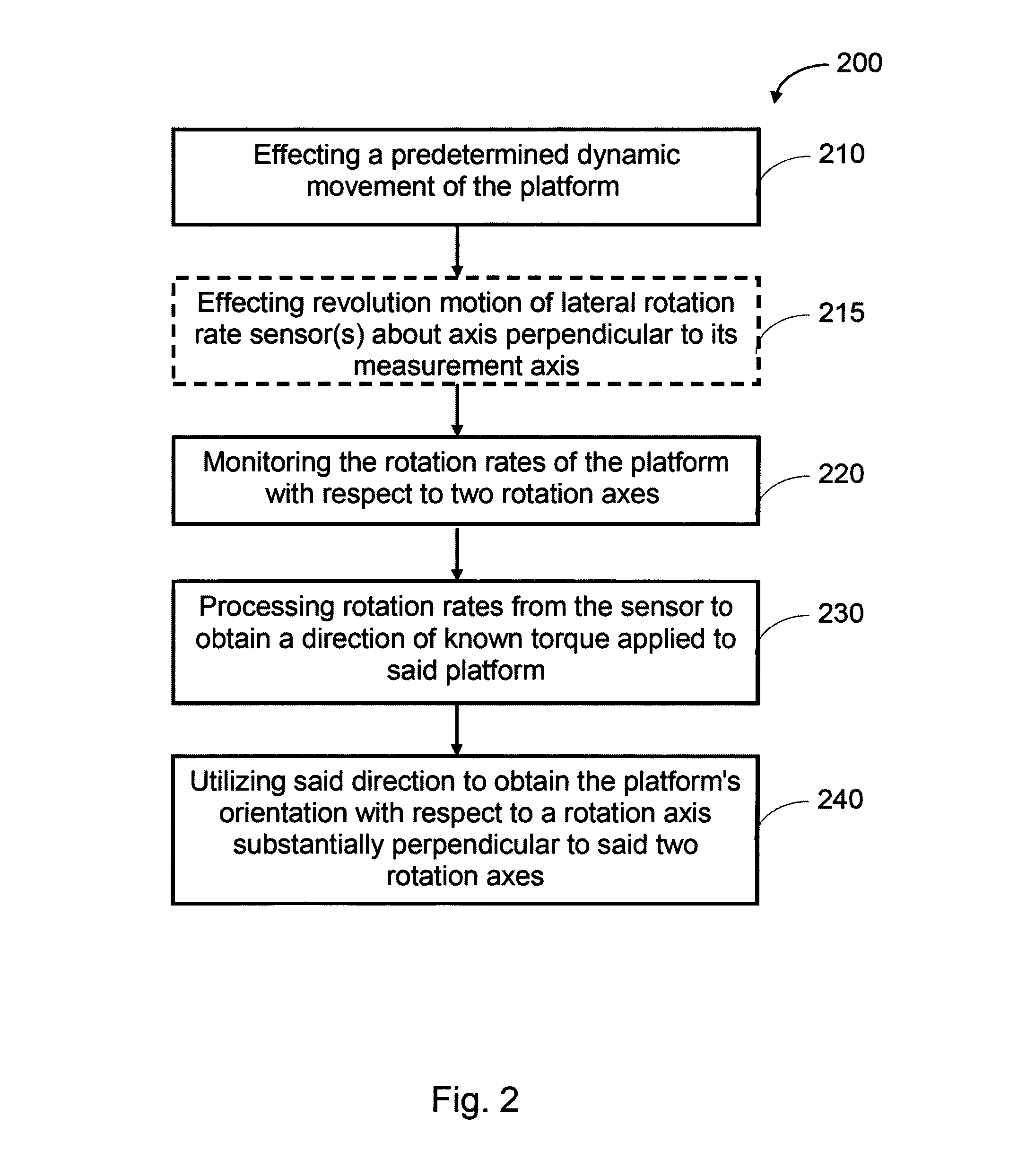
[0031]However, according to this technique, the body orientation is measured by the rate gyros which might have a bias drift impairing the measurement accuracy. Estimation of the bias of the roll rate gyro is carried out by statistical filtering algorithms (such as recursive Kalman-filtering) using the estimated gravity turn rate and the roll angle determined by the roll rotation rate gyros. The present invention utilizes the predetermined dynamic motion to provide precise measurements of the roll angle of the platform.
[0033]In this respect, it should be understood that in some cases, where the platform's movement is characterized by revolution of the platform about its longitudinal axis (e.g. bullet's or missile's spin), a so-called yaw of repose effect affects the equilibrium yaw orientation of the platform. This means that the platform's longitudinal axis deviates from the direction of its velocity vector by a certain deviation angle which may be computed based on the platform's velocity, its revolution rate, etc. According to the present invention, an accurate determination of the platform's roll orientation can be obtained by utilizing the direction of the platform's rotation with respect to the platform's longitudinal axis and then utilizing said deviation angle to determine said direction with respect to the platform's velocity vector.
[0039]The bias drift error ε is not modulated by the sensor's revolution, since it is associated with the sensor itself and not with the direction to which it is pointing (which changes during its revolution). Thus, in this case, the modulation of the measured data caused by the sensor's revolution would not affect any modulation of the constant bias drift error of the sensor, and hence the measurement data obtained from the sensor might be filtered (e.g. by band-pass filter) to suppress the contribution of the sensor's bias error ε. Accordingly, after suppression of the bias error, the measured data can be demodulated according to the sensors revolution rate, obtaining thereby an accurate signal Ψ0 associated with the platform's rotation rate. After acquiring Ψ0, the initial roll angle can be extracted from the phase φ (e.g. the initial roll angle may be represented by the phase φ).
[0049]Revolving the at least one rotation rate sensors with the angular velocity (ω) allows to reduce / suppress a bias effect of the sensor and to thereby increase the accuracy of the measurement provided by the sensor (e.g. the accuracy of measurement of the direction in the lateral plane). This is achieved by de-modulating the measured data from the revolving sensors and filtering out the contribution of its bias drift effect to thereby reduces / suppresses the bias drift and increase the measurement accuracy.
[0052]According to some embodiments of the invention, the determined angle of orientation of the aerospace platform with respect to the first axis is further utilized to compensate a bias drift effect of an additional rotation rate sensor that is associated with measurement of a rotation rate of the aerospace platform about its first rotation axis.

Problems solved by technology

However, the accuracy of systems that determine the platform's orientation based on the initial platform orientation, and on continuous sensing and integration of the platform's kinematics depends on the accuracy of the priory knowledge of the initial state and is generally deteriorating during the platform's motion.
This is due to errors of which the existing rotation rate sensors suffer (called bias drift effect) that impair their measurement accuracy.
In particular, when using integration of measured rotation rates over extensive periods of time to determine changes in the platform's angular position, the bias drift may accumulate to substantial bias measurement errors which require repeated bias corrections.
However, implementing an AHRS or INS with these types of rate gyros is extremely costly.
Such techniques are limited at least because they provide correction only to the measurement of the pitch and yaw rotation rates measurement, while not providing correction to the measured roll rotation rate.
However, relying on remote systems, such as GPS-based systems, does not provide sufficient integrity for driving systems with catastrophic failure modes, such as an AHRS.
However, determining the bias of the roll rate gyro bias is not nearly so straightforward.
The main disadvantages of this method are the need of the foreknowledge of the initial / intermediate roll angle which is often based on human judgment, which makes such systems cumbersome and susceptible to human error.
Also, they have relatively poor accuracy in the vicinity of the earth's magnetic poles.

Method used


Image

  • System and method for measurement of angular orientation of aerospace platforms
  • System and method for measurement of angular orientation of aerospace platforms
  • System and method for measurement of angular orientation of aerospace platforms

Examples


Embodiment Construction

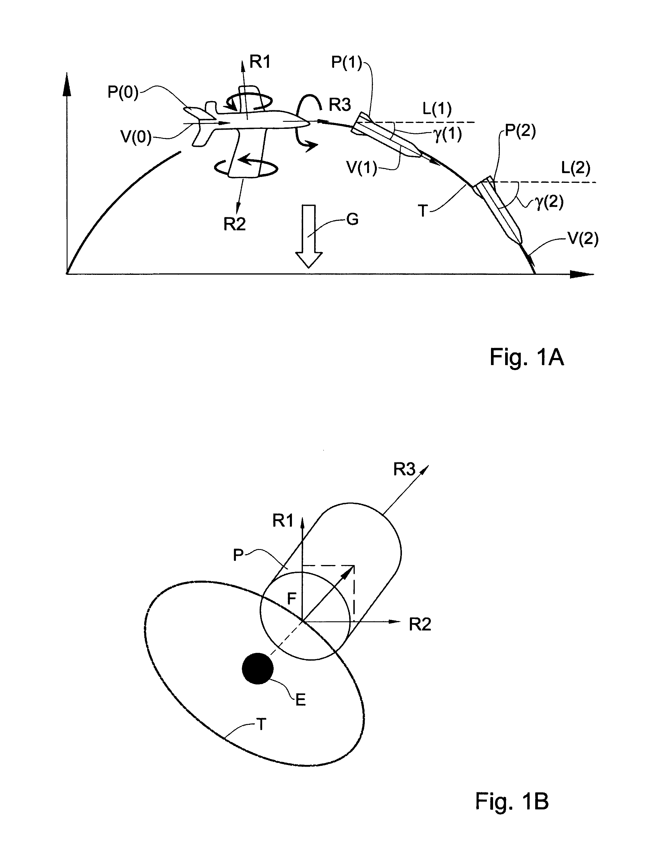
[0072]Reference is made now to FIGS. 1A and 1B, exemplifying the principles of the determination of a platform's orientation according to the present invention. FIG. 1A shows how these are implemented during a gravity turn motion of the aerospace platform; and FIG. 1B is a similar illustration during a satellite's controlled motion. To facilitate understanding, the same reference numbers are used to identify features common in all the examples described below.

[0073]FIG. 1A exemplifies the orientation determination technique of the present invention and how this is carried out during a ballistic motion of an aerial platform P (constituting an aerospace platform). Every stable airborne platform exhibits the gravity turn effect while in a free falling motion. The gravity turn effect acts on the aerial platform P, which moves along a ballistic trajectory T, affecting a predetermined dynamic motion of the platform. The predetermined dynamic motion, in this case, is characterized in that ...


PUM


Abstract

A method and system are presented for use in determination of the orientation of an aerospace platform with respect to a first rotation axis. A direction of a rotation rate vector of said aerospace platform within a lateral plane intersecting with said first rotation axis is measured and the measured data is analyzed to determine an orientation angle of said aerospace platform about said first rotation axis. While the aerospace platform is in a predetermined-dynamic state movement, a certain direction is determined by measuring a direction of the rotation rate of the aerospace platform within said lateral plane by a sensor assembly mounted on said platform and including at least one rotation rate sensor. An orientation of the platform with respect to said first axis is determined by determining a relation between said certain direction and said known direction within said external reference frame.

Description

FIELD OF THE INVENTION[0001]This invention relates to a method and a system for determining orientation of an aerospace platform.BACKGROUND OF THE INVENTION[0002]Angular measurements are required in a wide variety of aerospace platforms such as airplanes, missiles, satellites etc. Typically, measurement of the angular rotation rates of such aerospace platforms is carried out by Attitude Heading Reference Systems (AHRS) or Inertial Navigation Systems (INS) that utilize three orthogonal rotation rate sensors (e.g. rate gyros) which are adapted for measuring the rotation rates of the aerospace platform with respect to three rotation axes. Typically, three orthogonal rotation rate sensors are aligned along the roll, pitch and yaw rotation axes of the platform and are thus adapted for sensing the rotation rate of the platform with respect to these axes.[0003]Generally, having a priori knowledge of the platform's orientation, the orientation of the platform during its movement may be moni...

Claims


Application Information

Patent Timeline
Patent Type & Authority Patents(United States)
IPC IPC(8): G01C21/16G01C21/08
CPCG01C21/16G01C21/08G01C21/188G01C21/18
Inventor SHALTIEL, RABINKAHANE, ALLAN
Owner ISRAEL AEROSPACE IND
Learn More