
Antenna combiner

a combiner and antenna technology, applied in the field of satellite communication, can solve the problem that the signal-to-noise ratio (snr) of the antenna trying to receive the signal from the satellite may not be sufficien

Active Publication Date: 2018-11-13
KYMETA
View PDF25 Cites 13 Cited by
  • Summary
  • Abstract
  • Description
  • Claims
  • Application Information

AI Technical Summary

Benefits of technology

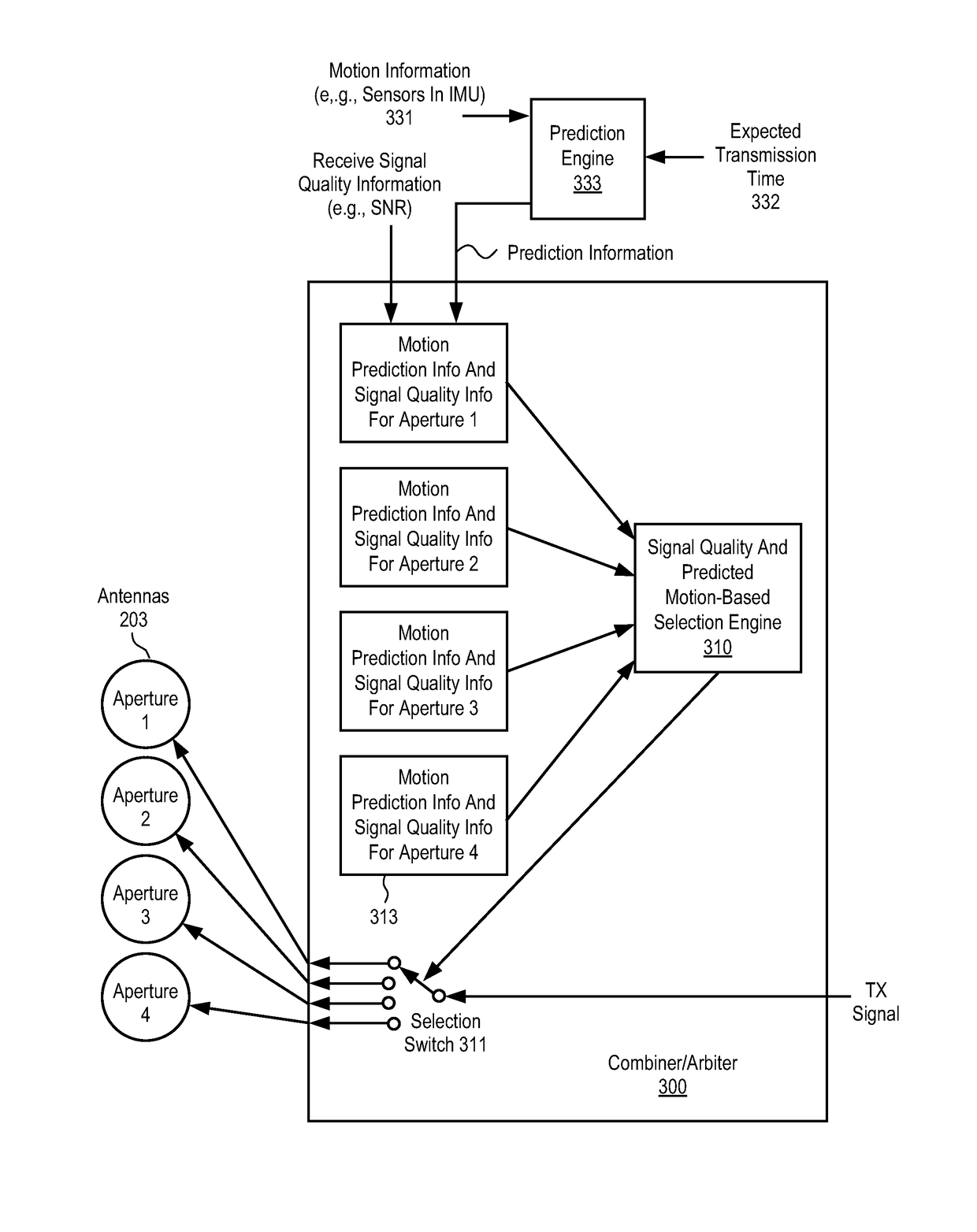
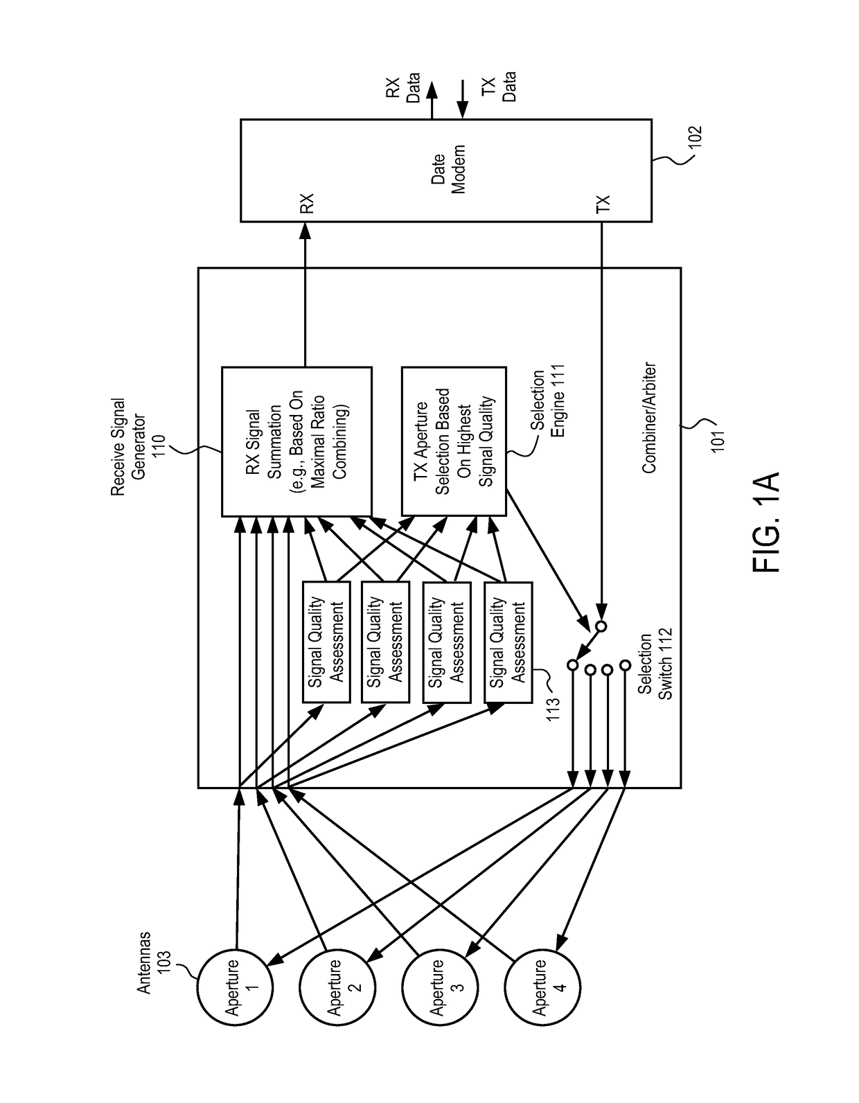
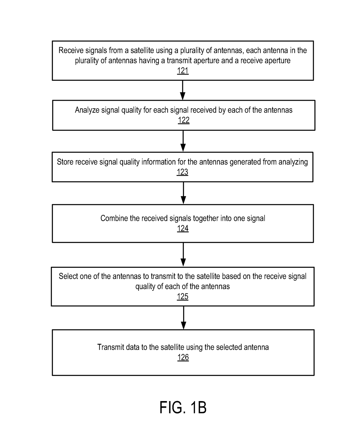
This patent describes a device called an antenna combiner that can decide which antenna to use for transmitting signals to a satellite. The device has multiple antennas that receive signals from the satellite, and each antenna has a transmit and receive aperture. The device also has signal analyzers that determine the quality of the signals from each antenna. An arbiter selects the best antenna to transmit to the satellite based on the signal quality. Finally, a first selector sends data to the selected antenna. The technical effect is that this device allows for efficient use of multiple antennas to transmit signals to a satellite.

Problems solved by technology

When this occurs, an antenna trying to receive the signal from the satellite may not have a signal-to-noise ratio (SNR) that is sufficient enough for the antenna to achieve a lock onto the satellite signal.

Method used


Image

  • Antenna combiner
  • Antenna combiner
  • Antenna combiner

Examples


examples of antenna embodiments

[0083]The techniques described above may be used with flat panel antennas. Embodiments of such flat panel antennas are disclosed. The flat panel antennas include one or more arrays of antenna elements on an antenna aperture. In one embodiment, the antenna elements comprise liquid crystal cells. In one embodiment, the flat panel antenna is a cylindrically fed antenna that includes matrix drive circuitry to uniquely address and drive each of the antenna elements that are not placed in rows and columns. In one embodiment, the elements are placed in rings.

[0084]In one embodiment, the antenna aperture having the one or more arrays of antenna elements is comprised of multiple segments coupled together. When coupled together, the combination of the segments form closed concentric rings of antenna elements. In one embodiment, the concentric rings are concentric with respect to the antenna feed.

Examples of Antenna Systems

[0085]In one embodiment, the flat panel antenna is part of a metamateri...


PUM


Abstract

An antenna combiner with transmission arbitration and method for using the same are described. In one embodiment, the apparatus comprises a plurality of antennas to receive signals from a satellite, each antenna in the plurality of antennas having a transmit aperture and a receive aperture, and wherein the receive aperture is operable to receive one of the signals from the satellite; a plurality of signal analyzers coupled to the plurality of antennas, each signal analyzer operable to determine signal quality of a distinct one antenna of the plurality of antennas; an arbiter coupled to the plurality of signal analyzers and operable to select one antenna of the plurality of antennas to transmit to the satellite based on results of determining the signal quality; and a first selector coupled to the arbiter and the plurality of antennas to cause data to be sent to the one antenna selected for transmission to the satellite.

Description

PRIORITY[0001]The present patent application claims priority to and incorporates by reference the corresponding provisional patent application Ser. No. 62 / 364,694, titled, “Antenna Combiner” filed on Jul. 20, 2016.FIELD OF THE INVENTION[0002]Embodiments of the present invention relate to the field of satellite communication; more particularly, embodiments of the present invention relate to radio frequency (RF) combining and transmit arbitration.BACKGROUND OF THE INVENTION[0003]When using electrically-steerable flat-panel antennas for satellite communications, there is often a need to provide communications links with performance that cannot be achieved with a single aperture. This may often be the case when there is a weak signal from the satellite. When this occurs, an antenna trying to receive the signal from the satellite may not have a signal-to-noise ratio (SNR) that is sufficient enough for the antenna to achieve a lock onto the satellite signal. A ground terminal's ability to...

Claims


Application Information

Patent Timeline
IPC IPC(8): H04B7/02H04B7/08H04B7/185H04B7/06
CPCH04B7/0604H04B7/0857H04B7/084H04B7/0868H04B7/0814H04B7/0608H04B7/1851H01Q3/2605H01Q13/103H01Q21/0012H01Q21/064H01Q5/42
Inventor ROTHAAR, BRUCEPRESTON, SHAWNBIALKE, NATHAN
Owner KYMETA
Learn More