Multi-section header with adjustable lateral frame relief

a lateral frame relief, multi-section technology, applied in the field of multi-section headers, can solve the problem of unsatisfactory free swinging of the lateral frame sections against the spring in the relief element, and achieve the effect of convenient stamping or cutting and functional reliability

Active Publication Date: 2018-12-04
CARL GERINGHOFF GMBH & CO KG
View PDF32 Cites 7 Cited by
  • Summary
  • Abstract
  • Description
  • Claims
  • Application Information

AI Technical Summary

Benefits of technology

[0009]In another pivot position of the stop element, a stop can be effective that delimits compression movement beginning at a certain pivot position and in a further pivot position a stop can be effective which limits a stretching movement beginning at a certain pivot position. For example, when transporting a header on roads, it is not desirable that a lateral frame section can elastically deflect in upward direction, but deflection in downward direction is definitely desired. When harvesting rapeseed, where the header must be maintained at a minimum height, it is conversely not desirable that a lateral frame section of the header elastically deflects in downward direction, but deflection in upward direction is however helpful.
[0011]According to one embodiment of the invention, the stop element is designed as a pivotable metal sheet that comprises a guide that, depending on the pivot position of the stop element, forms the respective stops. The metal sheet can be supported on a pivot bolt which is attached to the rigid spatial body. The metal sheet can be present in a doubled arrangement on opposite sides of the rigid spatial body wherein the construction is stabilized by a further connecting bolt. A guide can be easily stamped or cut by laser into a metal sheet. This embodiment as a whole is lightweight, inexpensive, and functionally reliable.
[0012]According to one embodiment of the invention, the stop element comprises at least a first pivot position, in which the stops are designed such that the spring travel of the spring from the zero position of the lateral frame section enables compression as well as stretching of the spring, and a second pivot position in which the stops are designed such that the spring travel of the spring from the zero position of the lateral frame section enables only compression or stretching of the spring. While the position of the stops in the first pivot position enables compression and stretching of the spring in both directions and insofar corresponds to the normal operation, the second pivot position provides the possibility to block either compression or stretching of the spring. In a third pivot position, an adjustment of the stop element in pivot positions is possible which correspond in a first pivot position to the normal operation, in a second pivot position to a blocking action of compression (stretching is still possible here), and a third pivot position to a blocking action of stretching (compression is still possible in this position).
[0015]According to one embodiment of the invention, the rigid spatial body is designed as a tube having the spring inserted in its interior. In this configuration, the distribution of forces between the lateral frame section and the central frame section is identical independent of whether the relief element provides a support action via the spring or the rigid spatial body. The spring is for this purpose stationarily connected with one end by a support bolt with the rigid spatial body and the other end is guided in the slotted hole. The spring is protected from dirt and corrosion in the tube interior. Also, the spring is shielded better in regard to injury risks for the operators.
[0018]According to one embodiment of the invention, individual stops in the guide form the stop for several adjusting ranges. The adjusting travels for adjustment of the adjusting ranges can be kept short in this way. The guide in the stop element is also compact.

Problems solved by technology

However, free swinging of the lateral frame sections against the spring in the relief element is not desirable in all situations of use of the header.

Method used


Image

  • Multi-section header with adjustable lateral frame relief
  • Multi-section header with adjustable lateral frame relief
  • Multi-section header with adjustable lateral frame relief

Examples


Embodiment Construction

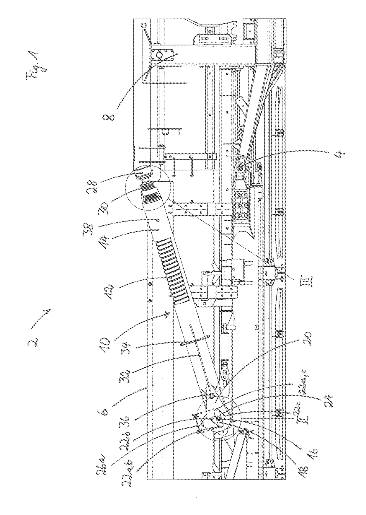
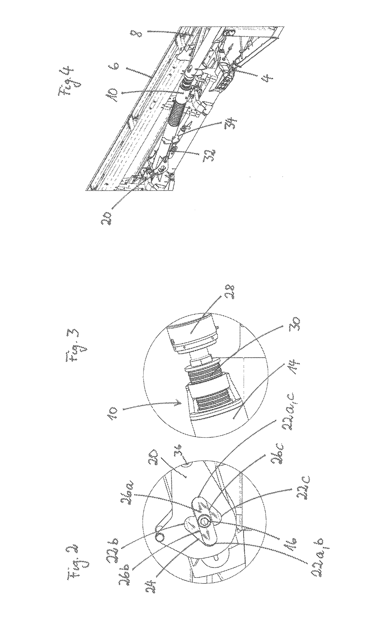
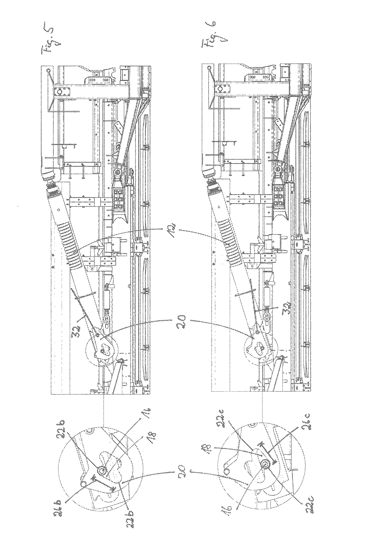
[0028]In FIG. 1 a partial view of a header 2 from the rear is shown. The header 2 is moved with its front side into the standing crop in order to cut the crop, gather it centrally, and move it to the rear into the intake channel of a harvester. The header 2 comprises a total working width which is comprised of the partial working widths of the frame sections that are joined with each other for articulation. A header 2 can be comprised, for example, of three or more frame sections that are articulated to each other. The lateral frame section 6 illustrated in FIG. 1 is connected to the central frame section 8 by a hinge 4. By means of hinge 4, the lateral frame section 6 can be pivoted with its free end in upward or downward direction.

[0029]The lateral frame section 6 is connected with the central frame section 8 additionally by a relief element 10. The relief element 10 transmits a portion of the weight of the lateral frame section 6 onto the frame of the central frame section 8. In ...


PUM


Abstract

A header has frame sections that are joined for articulation with each other. The frame sections each form a partial working width of the header. The frame sections include outer lateral frame sections and a central frame section. A relief element is connected to the central frame section and an outer lateral frame section adjacent to the central frame section. The relief element is adjustable between a springy setting and a locked setting. The relief element has a spring movable in a loading direction and also a spatial body rigid in the loading direction. The spring is connected to the first outer lateral frame section by a bolt guided in a slotted hole of the rigid spatial body. A pivotable stop element with stops is pivotable into a plurality of pivot positions. A spring travel of the spring is adjustable by the stops of the stop element.

Description

BACKGROUND OF THE INVENTION[0001]The present invention concerns a multi-section header with several frame sections that are joined with each other for articulation and each form a partial working width of the header, wherein outer lateral frame sections are connected with a central frame section with each other by means of a relief element that is adjustable between a springy setting and a locked setting.[0002]A header of the aforementioned kind is disclosed in U.S. Pat. No. 6,675,568. The header disclosed therein comprises a central frame section and two outer lateral frame sections joined for articulation thereto. Since the ground of a field across the total working width of the header does not remain flat upon forward travel of the harvester to which the header is attached in use, but can exhibit elevations and depressions, the individual frame sections with their partial working widths are supposed to better adapt to the soil contour by means of their articulated connection with...

Claims


Application Information

Patent Timeline
Patent Type & Authority Patents(United States)
IPC IPC(8): A01D41/14A01D57/20
CPCA01D57/20A01D41/144
Inventor SUDHUES, STEFFENSCHULZE RUCKAMP, JAN BERNDAMELINGMEYER, JENSSCHULZE SELTING, STEPHAN
Owner CARL GERINGHOFF GMBH & CO KG
Why Eureka
Try Eureka