Heat shield arrangement with sealing element

a technology of sealing element and heat shield, which is applied in the direction of mechanical equipment, machines/engines, light and heating equipment, etc., can solve the problems of leakage, increase the temperature of tiles, and the gap at the rim of tiles, so as to reduce the load of components, increase the life of components, and reduce the effect of cos

Inactive Publication Date: 2005-06-07
ROLLS ROYCE DEUT LTD & CO KG
View PDF24 Cites 43 Cited by
  • Summary
  • Abstract
  • Description
  • Claims
  • Application Information

AI Technical Summary

Benefits of technology

[0025]This design will reduce the load of the component, which may be used beneficially both for increasing its life and also for raising

Problems solved by technology

Generally, these designs are disadvantageous in that the tiles rise from the wall of the combustion chamber under thermal load.
Such leakage further increases the temperature of the tiles and, in turn, the gap at the tile rim.
Ultimately, failure of the tiles or heat shields will occur.
The above seals, which are fitted into lateral slots, are disadvantageous in terms of assembly and cooling.
This process incurs high effort and may be technically critical, in particular where the accessibility of the sealing slots of individual tiles is restricted.
These designs are further

Method used


Image

  • Heat shield arrangement with sealing element
  • Heat shield arrangement with sealing element
  • Heat shield arrangement with sealing element

Examples


Embodiment Construction

[0032]This detailed description should be read in conjunction with the details provided in the summary of the invention section above.

[0033]In the embodiments, the reference numerals apply to the same respective items.

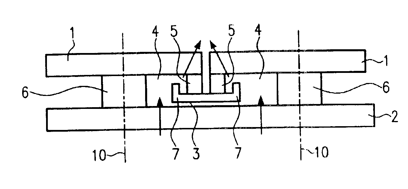
[0034]FIG. 1 is a schematic cross-sectional view of a wall 2, for example of a combustion chamber. Several tiles 1 are installed adjacent to each other on this wall, for example by means of fasteners 6. The assembly axes are each indicated by the reference numeral 10.

[0035]As becomes apparent from FIG. 1, the tiles are spaced at their adjacent rims 5.

[0036]An interspace 4 is provided between the wall 2 and the tile 1 through which cooling air is passed. The arrowheads schematically represent the cooling airflows. As becomes apparent, the seal according to the present invention will in no way impair effusion or transpiration cooling in the area of the tile rim. As regards the design of the cooling air ducts, any passages or the like, reference is made to the state of th...


PUM


Abstract

A heat shield arrangement includes several tiles 1 and several fasteners 6 for attaching the tiles at a spaced distance to a wall 2 to form an interspace 4 between the wall and the tiles which can be supplied with cooling air. At least one sealing element 3 is positioned between adjacent tiles 1 to provide a seal between rims 5 of the adjacent tiles 1. The rims 5 of the tiles 1 which are to be sealed are maintained at a spaced distance from the wall 2 by the fasteners 6 and the sealing element 3 is positioned remotely from the wall 2 and in abutment with the rims 5 of the tiles 1, with the sealing element 3 being allowed to float over the rims 5.

Description

[0001]This application claims priority to German Patent Application DE10155420.6, filed Nov. 12, 2001, the entirety of which is incorporated by reference herein.BACKGROUND OF THE INVENTION[0002]This invention relates to a heat shield arrangement with several tiles each being located on a wall and with at least one sealing element arranged between adjacent tiles, with the tiles being separated from the wall to form an interspace which can be supplied with cooling air.[0003]The heat shield arrangement applies to a hot-gas conducting structure, in particular a metallic component of a gas turbine system or a gas turbine combustion chamber.[0004]It is known from the state of the art that combustion chamber components, for example heat shields or tiles, are attached to the wall of a combustion chamber by a threaded connection without the use of sealing elements. Connection is accomplished by a bolt, with the rims of the tile directly abutting the wall of the combustion chamber. No sealing...

Claims


Application Information

Patent Timeline
IPC IPC(8): F23R3/00F23M5/00F23M5/04
CPCF23M5/00F23M5/04F23R3/002F23R2900/00012F23M2900/05005
Inventor GERENDAS, MIKLOS
Owner ROLLS ROYCE DEUT LTD & CO KG
Why Eureka
Try Eureka