Closure device for a container and furthermore a container fitted with the closure device

a technology for closing devices and containers, which is applied in the directions of caps, liquid handling, transportation and packaging, etc., can solve problems such as unintended opening of containers, and achieve the effect of reliable function

Inactive Publication Date: 2003-04-01
PARAT WERK SCHOENENBACH GMBH CO KG
View PDF21 Cites 45 Cited by
  • Summary
  • Abstract
  • Description
  • Claims
  • Application Information

AI Technical Summary

Benefits of technology

One object of the invention is to provide a closure device for a container which is reliable in its function.
Although in principle it would be possible to design the at least one actuating member in the form of a plain slide, specific advantages are to be had with a design, in which the actuating member is designed in the form of a pivotally mounted lever, whose first lever arm cooperates with a first engagement element and whose second lever arm is provided with an abutment part. The switching over motion of the actuating member is in this case a sort of rocking movement, something which offers the advantage that, unlike the case of a sliding movement, the overall length of the first locking instrumentalities may be made relatively small so that closure device only requires a small amount of space. Furthermore, it is possible to do without complicated sliding bearing means, since it is possible to have recourse to a pivot bearing which is simpler to design.

Problems solved by technology

Since in the case of the known closure device the locking action is only ensured by the resilient effect due to the pivotal first engagement members, damage to such resilient means can lead to an unintended opening of the container.

Method used


Image

  • Closure device for a container and furthermore a container fitted with the closure device
  • Closure device for a container and furthermore a container fitted with the closure device
  • Closure device for a container and furthermore a container fitted with the closure device

Examples


Embodiment Construction

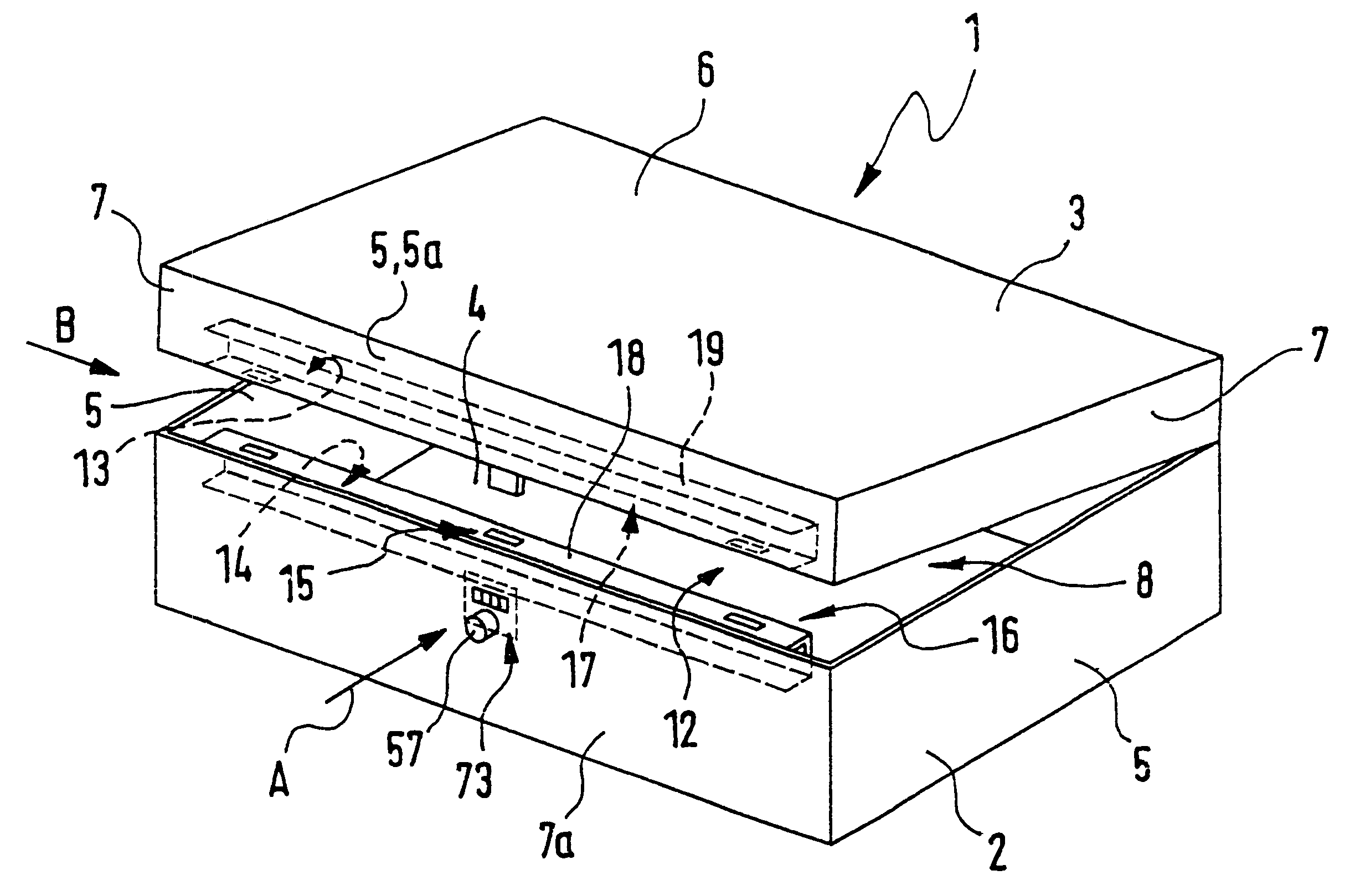
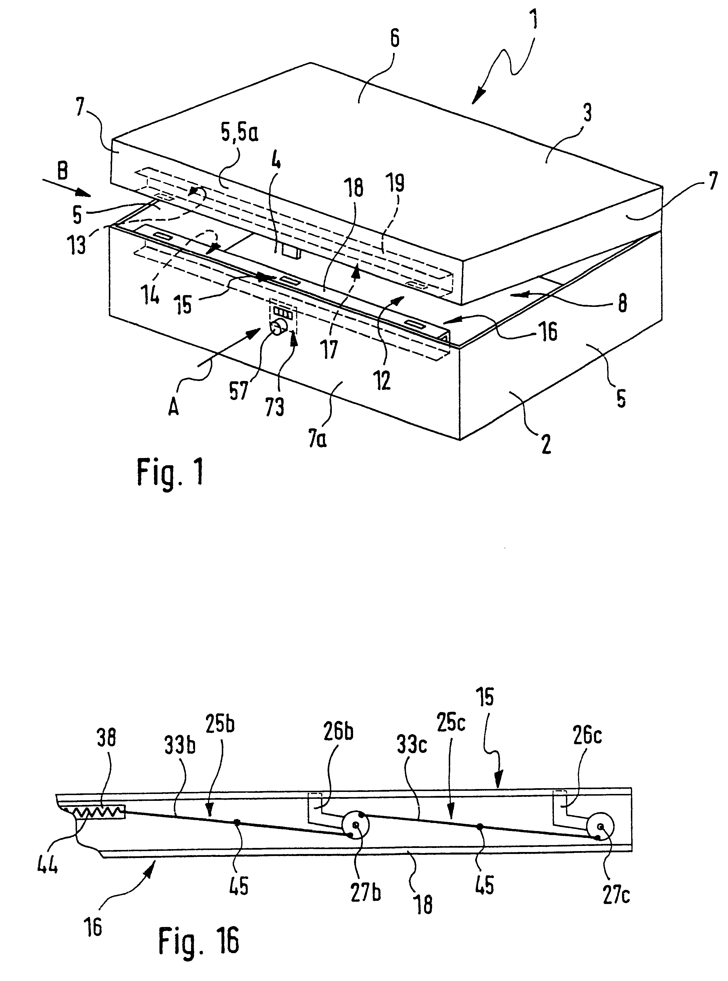
FIG. 1 shows a container 1 which is for example in the form of a valise or a tool chest and which comprises a first container part 2 and a second container part 3. In the working embodiment illustrated the two container parts 2 and 3 are each designed in the form of shells, the sharp edges shown in the drawing being rounded off if desired.

The first container part 2 constitutes a bottom container part with a floor wall 4, having a rectangular plan and from whose edges in all four first side walls 5 extend away to the same side.

In the working embodiment illustrated the second container part 3 defines the top container part, which has a top wall 6 corresponding to the plan of the floor wall 4 and fourth second side walls extending away to the same side.

The side walls 5 and 7 are only partly visible. The container parts 2 and 4 are so arranged in relation to each other that when the container is closed the first and the second side walls 5 and 7 face each other and have their free edges...


PUM

PropertyMeasurementUnit
displacementaaaaaaaaaa
resilient forceaaaaaaaaaa
resilient effectaaaaaaaaaa

Abstract

A closure device for a container, which possesses a locking element for mutually locking of two container parts when the container is closed. The locking element has first and second locking instrumentalities, which are arranged on the different container parts. By way of an actuating member, which is able to be switched over between a closed position and an open position a first engagement member may be shifted between a locking position and a released position. The open position of the actuating member corresponding to the locking position may be secured by an obstructing member in order to prevent unauthorized unlocking of the container. An opening mechanism renders possible an overriding of the obstructing action and a switching over of the actuating member into the open position.

Description

The invention relates to a closure device for a container, as for example a travelling case or a tool case, comprising a locking means for the releasable mutual locking of the two container parts when the container is closed, said locking means having first locking instrumentalities for the first container part and second locking instrumentalities for the second container part, the first locking instrumentalities including at least one actuating member able to be switched over between an open position and a closed position, said actuating member being kinematically coupled with at least one engagement member of the first locking instrumentalities, which in the open position of the actuating member can assume released position out of locking engagement with a second engagement member of the second locking instrumentalities and in the closed position of the actuating member can assume a locking position in locking engagement with the second engagement member.Furthermore, the invention...

Claims


Application Information

Patent Timeline
Patent Type & Authority Patents(United States)
IPC IPC(8): A45C13/00A45C13/06E05B65/52E05B65/00E05C9/18E05C9/00E05C9/04E05C9/16
CPCA45C13/06E05B65/5261E05C9/1883E05C9/04Y10T292/0832Y10T292/0829Y10T292/0862Y10T292/1076Y10T292/0946Y10T292/0848Y10T292/081Y10T292/0801Y10T292/0828Y10T292/0849Y10T292/0825Y10T292/0853
Inventor PAUSER, HERBERT BERHARD
Owner PARAT WERK SCHOENENBACH GMBH CO KG
Why Eureka
Try Eureka