Motor pump unit

a technology of motor pump and pump body, which is applied in the direction of pumping plant, water supply tank, valve details, etc., can solve the problems air can be trapped in oil, and the intrusion of trapped air cannot be reliably avoided, so as to achieve the effect of reducing the supply efficiency of radial piston pump

Inactive Publication Date: 2003-02-25
HEILMEIER & WEINLEIN FAB FUR OEL HYDRAULIK
View PDF12 Cites 46 Cited by
  • Summary
  • Abstract
  • Description
  • Claims
  • Application Information

AI Technical Summary

Problems solved by technology

After long resting periods of the motor pump unit, or when tilting or moving the motor pump unit, air can be trapped in the oil.
The intrusion of trapped air cannot be avoided reliably even by using downwardly extending suction tubes for the radial pist

Method used


Image

  • Motor pump unit
  • Motor pump unit
  • Motor pump unit

Examples


Embodiment Construction

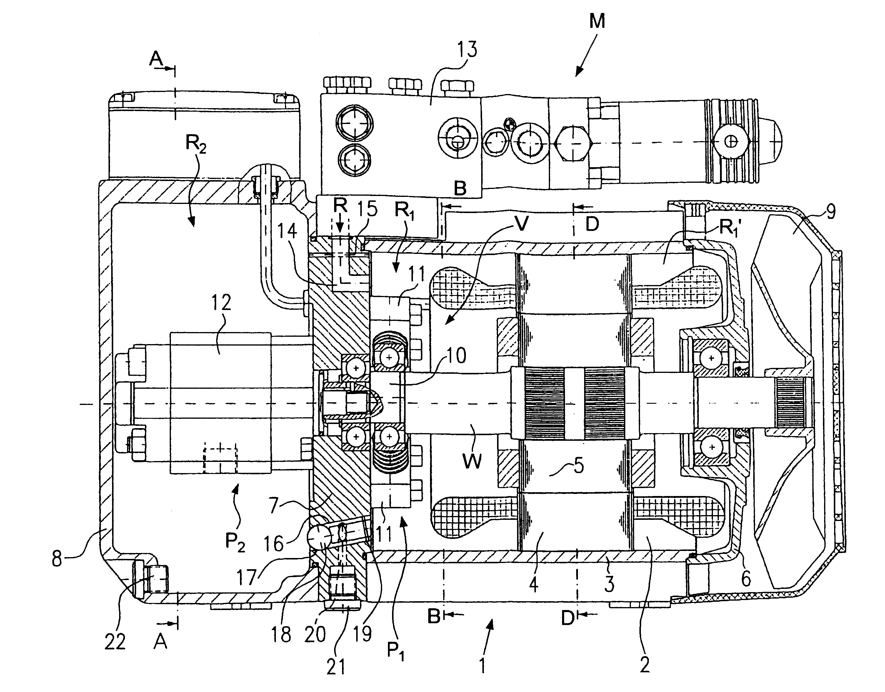
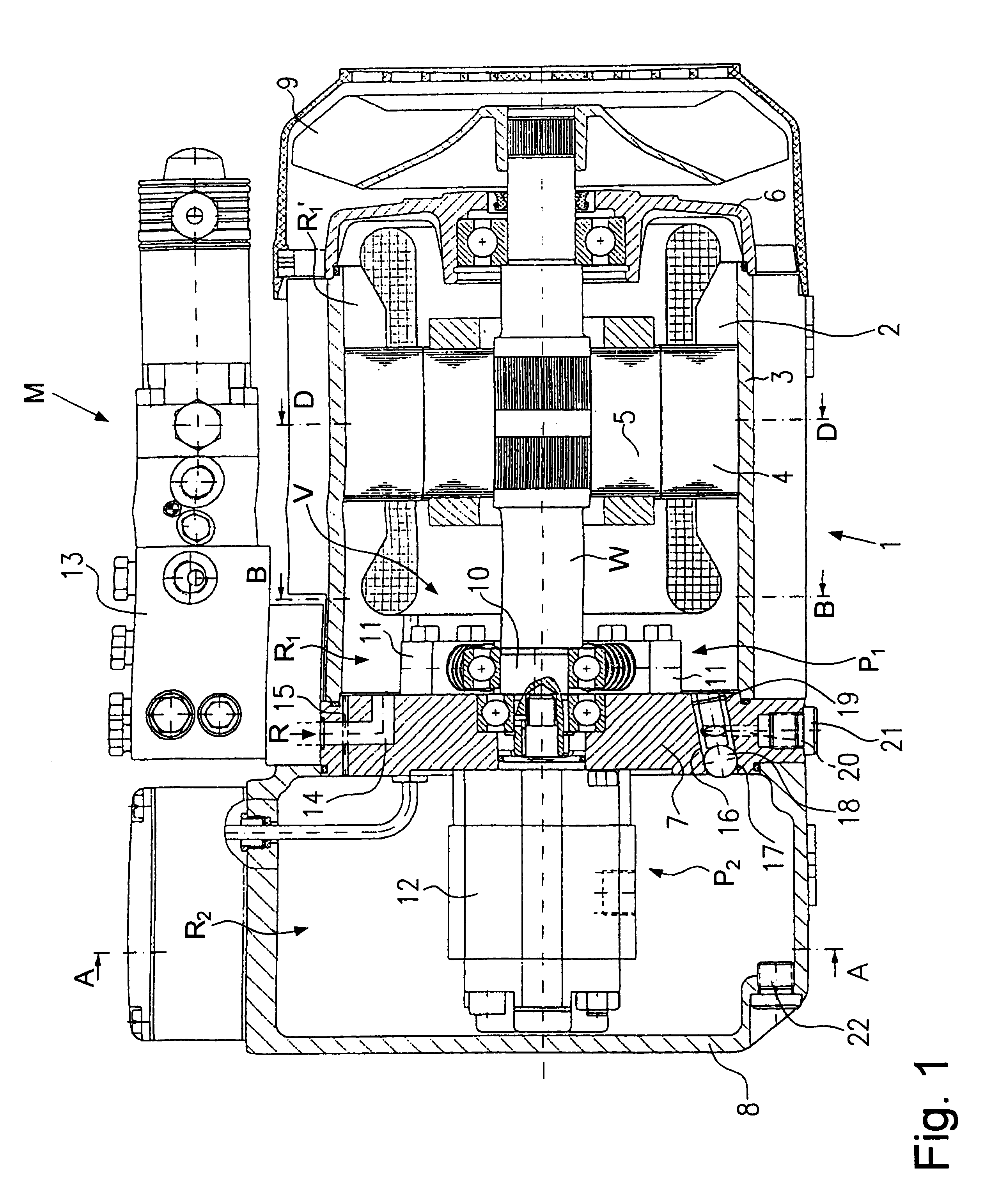
A motor pump unit M in FIG. 1, e.g., is a portable unit having a weight below about 25 kilos and is intended for a lying operation position. The motor pump unit, however, does not need to be necessarily a portable unit. Furthermore, it can be developed for an upright operation position.

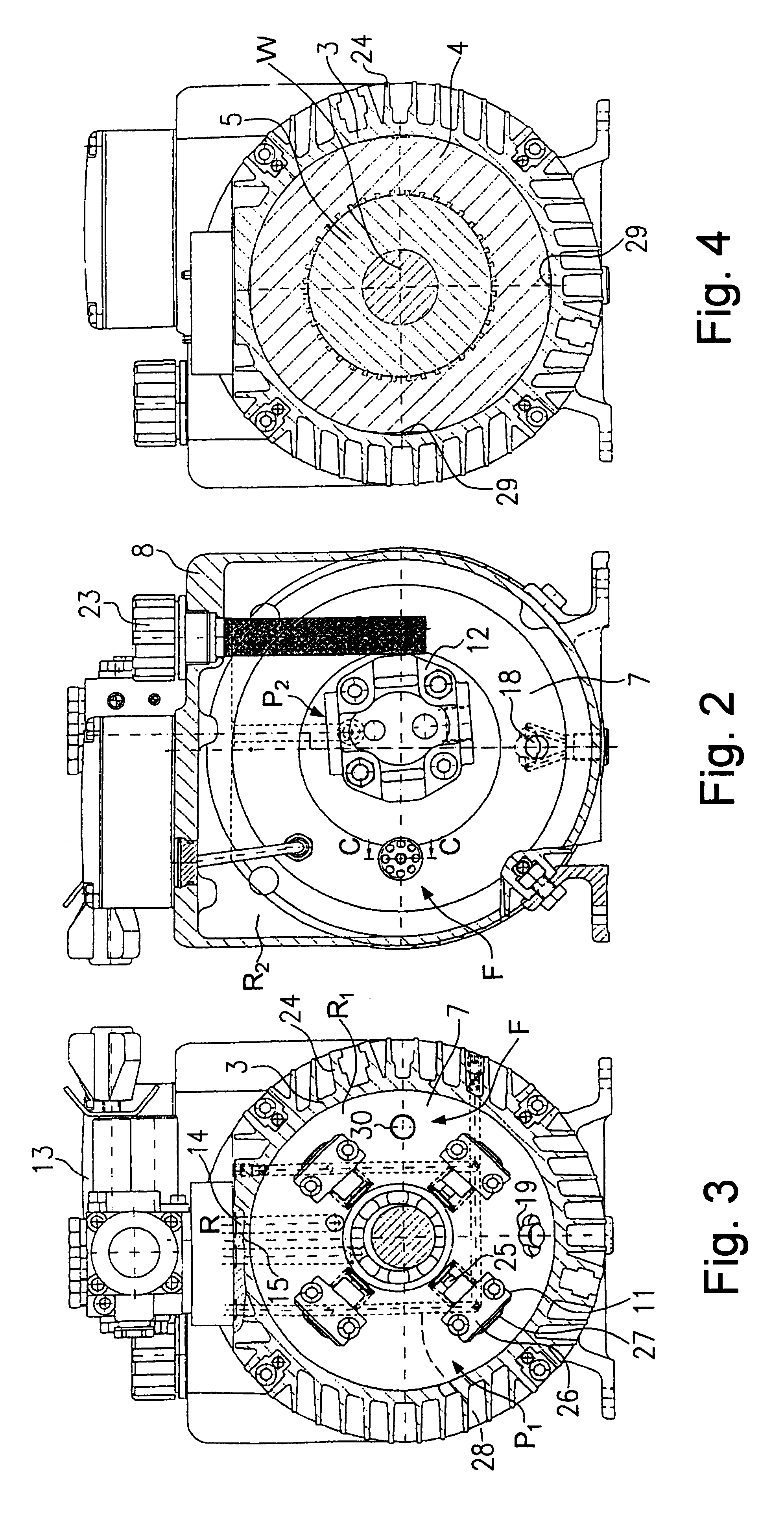
In a housing 1 confining an oil reservoir an electric motor 2 is situated. The electric motor 2 is designed as an oil immersible motor and serves as a drive for a radial piston pump arrangement P1 (high pressure stage) and a low pressure stage P2, e.g., defined by a gear wheel pump 12. A motor shaft W is situated essentially horizontally. Housing 1 includes a light metal profile section 3 (rib tube) with cylindrical inner wall. A stator winding part 4 of electric motor 2 directly is shrunk into the light metal profile section 3. A rotor 5 is centered within stator winding part 4 on motor shaft W. Motor shaft W is supported in bearings in an end cap 6 and a separation wall 7 of the housing 1. A further...


PUM


Abstract

A motor pump aggregate M has a housing 1 defining an oil reservoir with first and second chambers R1, R2. An electromotor 2 is driving via its motor shaft W at least one radial piston pump arrangement P1 provided within said first chamber R2. Both chambers R1, R2 are separated by a separation wall 7. A filling and pressure biasing system V is provided for said first chamber R1 in order to adjust within said first chamber R1 a predetermined oil filling level and a pre-selected oil pressure pre-biasing for said radial piston pump arrangement P1.

Description

1. Field of the InventionThe present invention relates to a motor pump unit in which a housing has first and second chambers defining an oil reservoir separated by a separation wall, and an electric motor for driving a radial piston pump arrangement within the first chamber.2. Description of the Related ArtIn the motor pump unit disclosed in DE 299 06 881 U, oil returning from a hydraulic system either directly flows into a first chamber or finally flows into the first chamber from a second chamber via a lower open passage in a separation wall between the first and second chambers. In a horizontal operation position of the motor pump unit the same filling level is achieved in both chambers. A ventilation bore situated in an upper portion of the separation wall allows air to pass through. The ventilation bore has a significantly smaller cross-section than the passage in the separation wall. A radial piston pump provided within the first chamber has to generate extremely high hydrauli...

Claims


Application Information

Patent Timeline
IPC IPC(8): F04B23/10F04B23/02F04B23/00
CPCF04B23/103F04B23/021Y10T137/7559Y10T137/86147
Inventor NEUMAIR, GEORG
Owner HEILMEIER & WEINLEIN FAB FUR OEL HYDRAULIK
Why Eureka
Try Eureka