Material tray supply device for chip recording equipment

Pending Publication Date: 2019-01-18
广州明森合兴科技有限公司
View PDF5 Cites 6 Cited by
  • Summary
  • Abstract
  • Description
  • Claims
  • Application Information

AI Technical Summary

Problems solved by technology

[0004] 1. Since both the chip tape roll and the receiving mechanism need to be rotated to release and collect the chip tape, the entire supply device cannot be too close to the processing station of the chip programming equipment, and a certain distance is required to realize the rotation Release chip belt and collect chip belt, resulting in too bulky and not compact enough for the whole device
[0005] 2. The release and collection of the chip rolls need to be realized by setting the corresponding runners, resulting in a complex structure
[0006] 3. Control the movement of the chip tape to the feeding station by controlling the rotation of the chip tape roll, resulting in poor positioning accuracy of the chip, which is not conducive to subsequent chip handling; at the same time, if the fixed-frame conveying method is used to realize the chip on each processing station When transferring, and each processing station processes multiple chips at the same time, it is necessary to set up multiple chip tape rolls in order to have multiple chips corresponding to the processing stations on the loading station to achieve fixed-frame transportation. Obviously Using the method of releasing the chip tape to realize the chip loading will lead to a more complicated structure, and it will not be possible to achieve accurate fixed-frame delivery

Method used


Image

  • Material tray supply device for chip recording equipment
  • Material tray supply device for chip recording equipment
  • Material tray supply device for chip recording equipment

Examples


Embodiment 1

[0035] The tray supply device of the chip programming device in this embodiment includes a fixed frame, a tray sending module, and a tray delivery module; wherein,

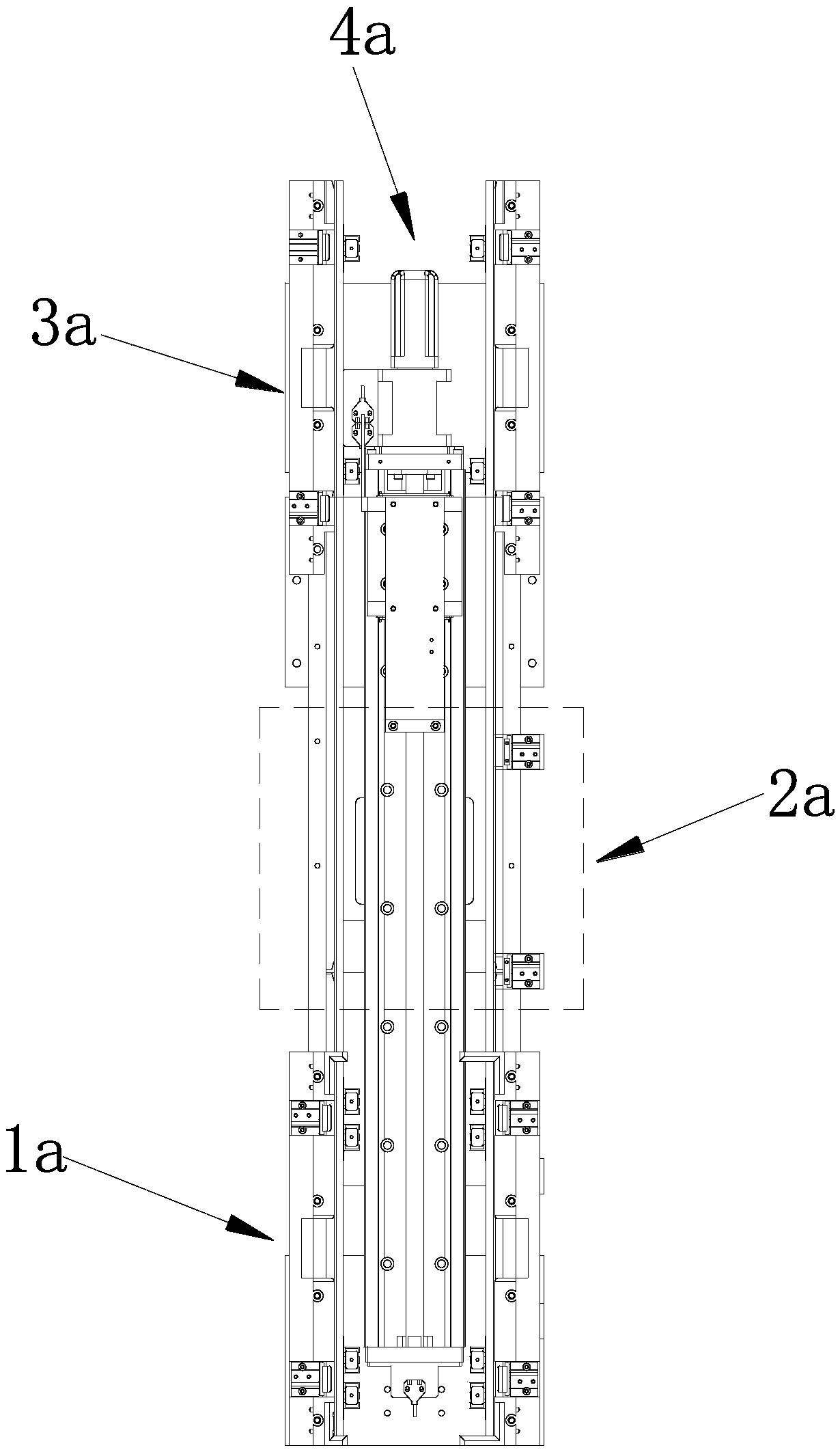
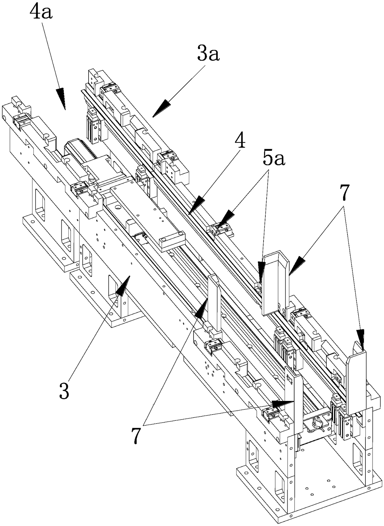
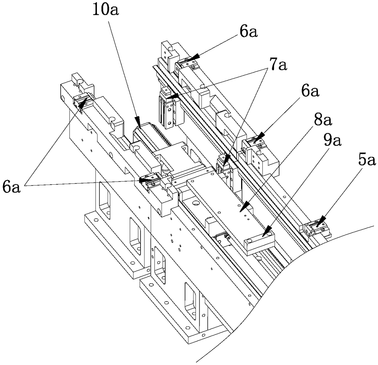
[0036] see Figure 1-Figure 7 , the tray delivery module 1a includes a tray mechanism and a tray distribution mechanism; the tray mechanism includes a pallet 1 and a lateral drive mechanism 2 that drives the pallet 1 to perform telescopic movement, and the chip trays to be sent out are stacked on the tray in turn plate 1; the tray distribution mechanism is arranged below the chip tray, including a support plate and a vertical drive mechanism that drives the support plate to move vertically; during the vertical movement of the support plate, a handover limit Point A and the offer limit point B below the handover limit point A. When the support plate moves to the handover limit point A, the support plate is flush with the pallet 1. When the support plate moves to the offer limit point At position B, the supporting ...

Embodiment 2

[0053]The difference between this embodiment and Embodiment 1 lies in that: the longitudinally moving plate is lower than the limit point of the offer, and higher than the lowest point of the transition plate. When the chip tray to be sent is handed over to the transition plate, the first vertical drive mechanism drives the transition plate to move downward. During the downward movement, the chip tray on the transition plate is transferred to the longitudinal moving plate, and then The longitudinal driving mechanism drives the longitudinal moving plate to move forward to the loading station to complete the supply of the chip tray; when the chips on the chip tray are transported away, the longitudinal driving mechanism drives the longitudinal moving plate to move forward to the collecting station. position, the empty chip trays are collected and processed by the tray collection module.


PUM


Abstract

The invention discloses a material tray supply device for chip recording equipment. The device comprises a material tray send-out module and a material tray conveying module; the material tray send-out module comprises a support mechanism and a material tray distribution mechanism; the support mechanism comprises support plates and transverse driving mechanisms for driving retractable movement ofthe support plates, and chip material trays to be sent out are sequentially stacked on the support plates; the material tray distribution mechanism is disposed below the chip material trays and comprises supporting plates and vertical driving mechanisms for driving the supporting plates to move vertically; the material tray conveying module includes a longitudinal moving plate and a longitudinal driving mechanism for driving the longitudinal moving plate to move. The chip material trays which are stacked together are sent out one by one and then conveyed to feeding stations, supply of the chipmaterial trays is achieved, the structure is simple, the occupied space is small, convenience is provided for cooperative installation with a processing module of the chip recording equipment, and improvement of the supply efficiency and transport efficiency of chips is facilitated.

Description

technical field [0001] The invention relates to a chip programming device, in particular to a material tray supply device of the chip programming device. Background technique [0002] With the advancement of science and technology, more and more electronic products appear in front of people, and chips are an important part of most electronic products, which store a large amount of data. Before the chip leaves the factory, the corresponding data needs to be burned on the chip through the burning equipment, so the burning equipment is very important for the processing of the chip. [0003] In the existing chip programming equipment, the supply of chips is generally delivered to the feeding station in sequence by releasing the chip tape and waiting for the handling of the feeding mechanism. At the same time, it is also necessary to set up a receiving mechanism The spare chip belt is recycled for subsequent processing, but the following deficiencies still exist: [0004] 1. Si...

Claims


Application Information

Patent Timeline
Patent Type & Authority Applications(China)
IPC IPC(8): B65G59/06
CPCB65G59/062B65G2201/0258
Inventor 王开来吴伟文李宇婕李守东
Owner 广州明森合兴科技有限公司
Why Eureka
Try Eureka