

Solar distributed point focusing optical lens tracing vacuum tube utilizing system
A technology of solar tracking and solar mirror, applied in the field of solar energy utilization, can solve the problems of no solution focus, impossible tracking, and difficult city promotion
- Summary
- Abstract
- Description
- Claims
- Application Information
AI Technical Summary
Problems solved by technology
Method used
Image

Examples
Embodiment 1
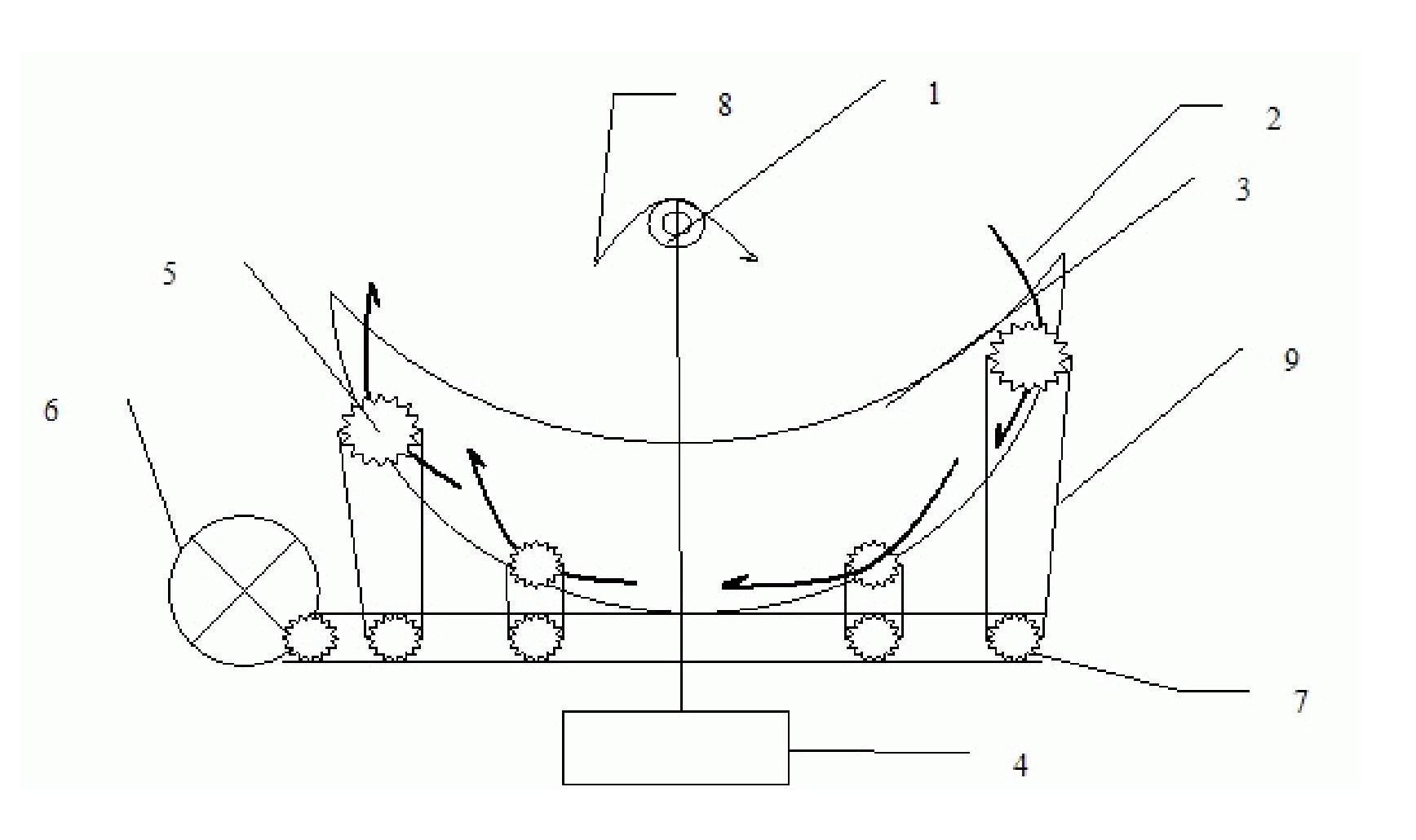
[0058] Single-axis tracking multi-parabolic mirror solar point focusing vacuum tube utilization system (side view)
[0059] this figure 1 It is a side view. The solar mirror is a group of solar energy utilization systems composed of four parabolic mirrors (2), vacuum tube utilization system (1), and solar mirror brackets; the system is installed on a building and integrated with the building The solar energy utilization equipment (1) is a vacuum tube, which is a glass tube with a vacuum interlayer. A solar selective coating is arranged inside the vacuum interlayer. There is a fluid or heat pipe inside the vacuum tube for heat exchange. The outside of the vacuum tube is provided with The vacuum tube is used for heat insulation; the vacuum tube is installed on the building and kept still; the parabolic mirror is installed on a parabolic device (3), and each parabolic mirror is provided with a rotating shaft (5), and the solar mirror can be arranged along Rotating along the shaft (5...
Embodiment 2
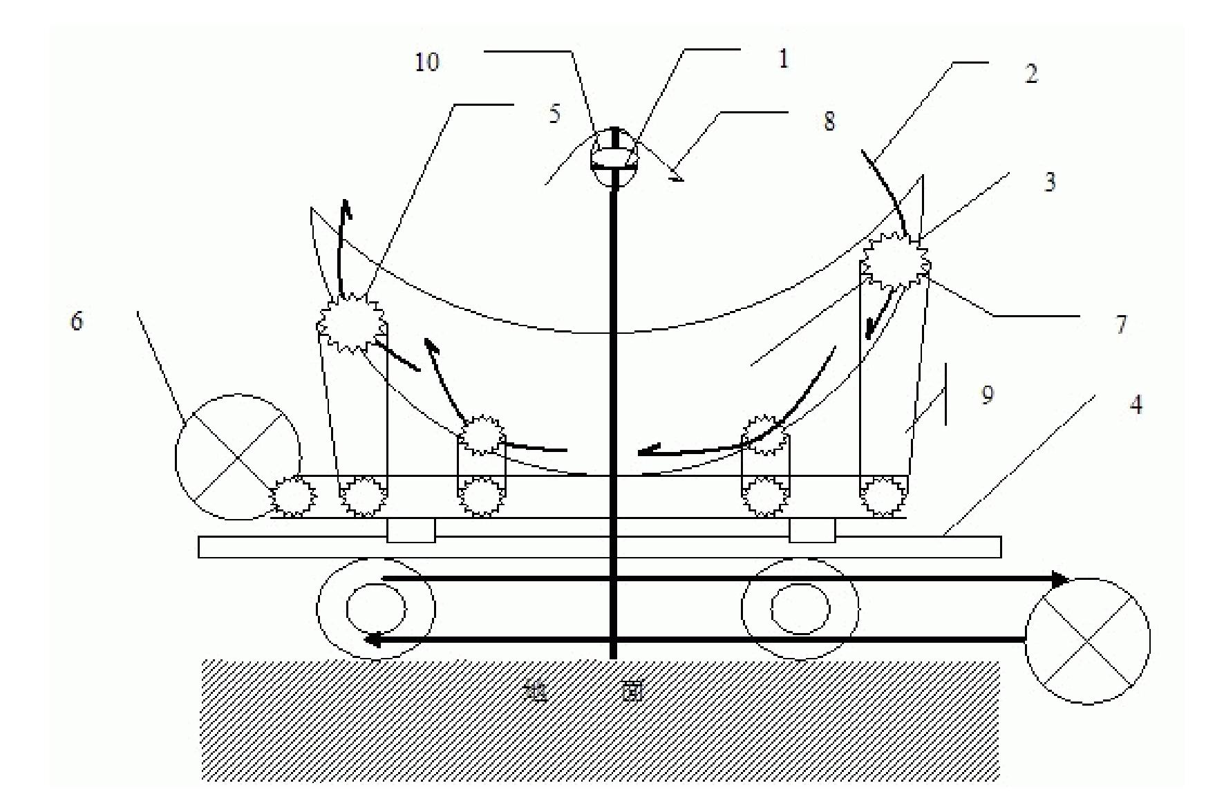
[0061] Dual-axis tracking multi-parabolic mirror solar point focusing vacuum tube utilization system (side view)
[0062] this figure 2 It is a side view. The solar mirror is a group of solar energy utilization systems composed of four parabolic mirrors (2), vacuum tube utilization system (1), and solar mirror brackets; the system is installed on a building and integrated with the building The vacuum tube is equipped with a vacuum tube to heat the insulation box; the vacuum tube is set on the building and kept still; the parabolic mirror is set on a parabolic device (3), and each parabolic mirror is provided with a rotating shaft (5) The solar mirror can be rotated along the rotating shaft (5). Multiple solar mirrors can track solar energy through different motions, and at the same time focus solar light on the vacuum tube. The four parabolic mirrors use the same drive system to transmit The mechanism is a gear set, and different solar mirrors have different gear teeth numbers, ...
Embodiment 3
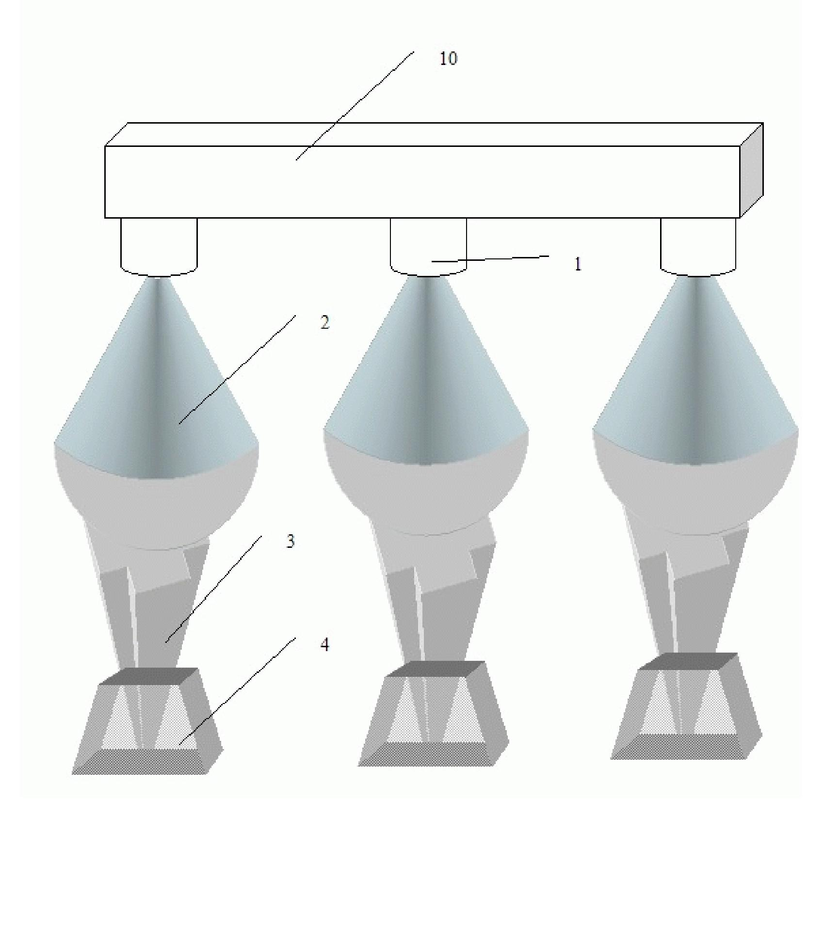
[0063] Embodiment three, heat transfer hot spot focus tracking array tracking
[0064] Such as image 3 , This case is a solar energy utilization system composed of multiple point focusing mirrors installed on the building. The solar mirror (2) is a parabolic mirror focused on the sampling point, and each point focusing mirror is set on the tracking system (3) , The tracking system is set on the tracking bracket (4), each solar mirror focuses solar energy on a vacuum tube utilization system (1), the vacuum tube system converts solar energy into heat energy, and then the heat energy is transmitted by the heat pipe heat transfer system (10), Multiple vacuum tubes are arranged on different point focusing systems to realize light-to-heat conversion, and then the heat pipe system is used to realize the transmission and utilization of heat energy. By setting up multiple groups of solar energy in different buildings and ground areas, it is possible to achieve spot-focused utilization of...
PUM
 Abstract
Description
Claims
Application Information