Distributed solar point focusing optical mirror heat pipe tracking and utilizing system

A solar heat pipe and solar tracking technology, applied in the field of solar energy utilization, can solve the problems of limited application, unresolved focus, and inability to achieve tracking

Inactive Publication Date: 2010-12-01
BEIJING WISWORD HI TECH
View PDF6 Cites 2 Cited by
  • Summary
  • Abstract
  • Description
  • Claims
  • Application Information

AI Technical Summary

Problems solved by technology

This technology is mainly suitable for large-scale power generation, not suitable for small-scale regional applications, especially not suitable for solar power generation and cogeneration power generation in cities, thus limiting its application
[0004] Chinese patent 200710176966 provides a combined tracking system, which can be used in a trough-type and tower-type tracking system. The tracking method adopts the method of keeping the focal line fixed while the solar mirror system moves, mainly on the ground. Two orbits are set for tracking, and the trough system point focusing system uses its linear axis to be placed parallel to the earth's autobiographical axis, so it can use rotation in one direction to achieve tracking, but this scheme uses rotation on the ground to achieve trough tracking , obviously tracking cannot be realized, so the inventor further set pitch tracking in the scheme, so that the trough system is not a one-way tracking, but a two-way tracking, so the inventor did not solve the tracking problem that the focus does not move when the trough one-way tracking question
[0005] The existing focused solar energy utilization technology is mainly applied to large-scale power generation. Usually, a 1WM power station requires an area of ​​60 mu. Such an area requirement is difficult to promote in cities, so it needs to be based on the land requirements of cities , to provide a solar energy concentration utilization system suitable for urban land requirements

Method used


Image

  • Distributed solar point focusing optical mirror heat pipe tracking and utilizing system
  • Distributed solar point focusing optical mirror heat pipe tracking and utilizing system
  • Distributed solar point focusing optical mirror heat pipe tracking and utilizing system

Examples


Embodiment 1

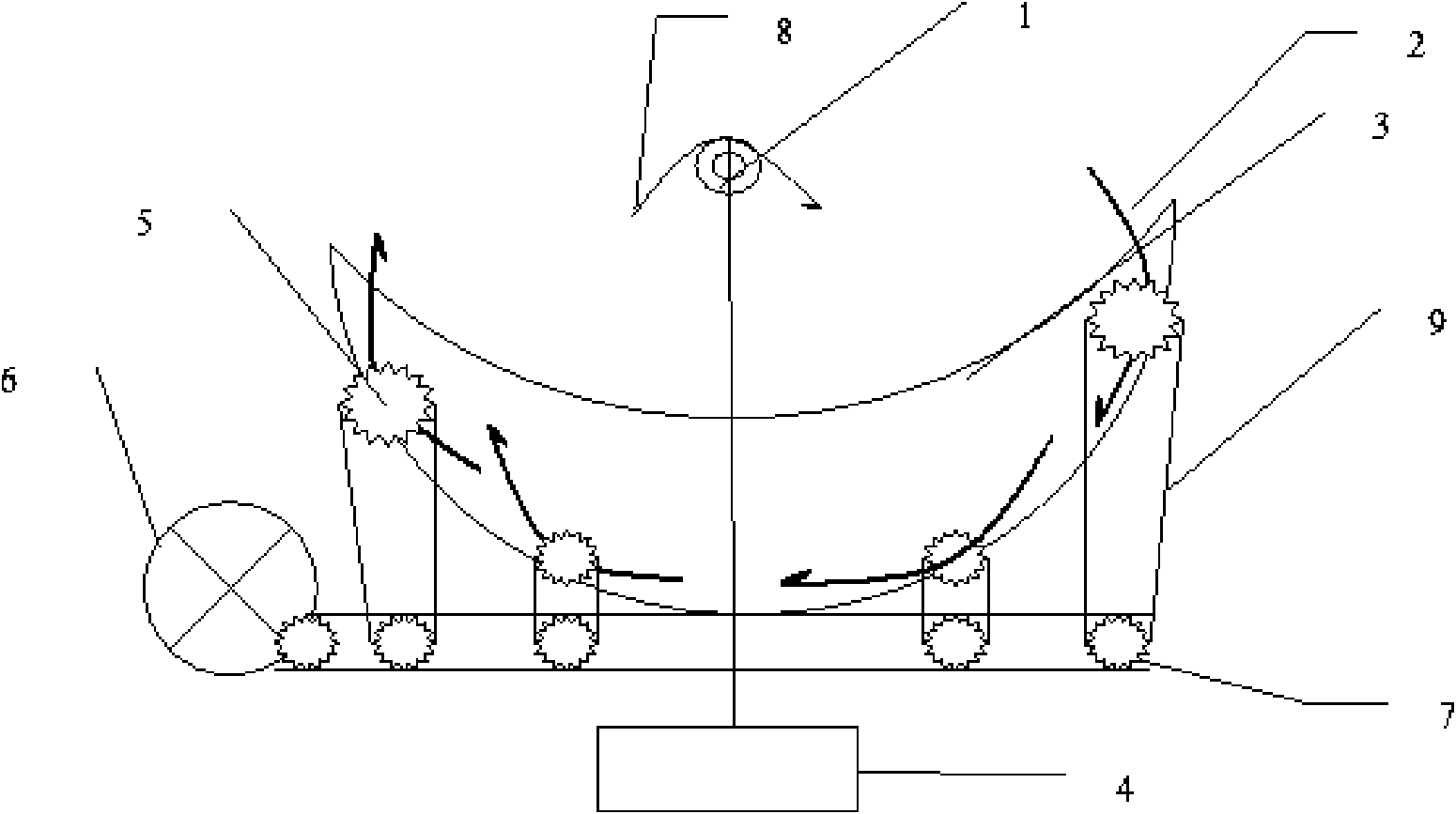
[0055] Single-axis tracking multi-parabolic mirror solar point focusing heat pipe utilization system (side view)

[0056] Book figure 1 It is a side view, and the solar mirror is a group of solar energy utilization systems composed of four parabolic reflectors (2), heat pipe utilization system (1), solar mirror bracket, etc.; the outside of the heat pipe is provided with a vacuum tube to insulate the heat preservation box; the parabolic mirror Set on a parabolic device (3), each parabolic mirror is provided with a rotating shaft (5), the solar mirror can rotate along the rotating shaft (5), and multiple solar mirrors realize solar energy through different movements Tracking, focusing solar light on the heat pipe at the same time, the four parabolic mirrors use the same drive system, the transmission mechanism is a gear set, different solar mirrors have different gear teeth, so that different speeds can be used to drive different solar mirrors for movement . Distributed solar...

Embodiment 2

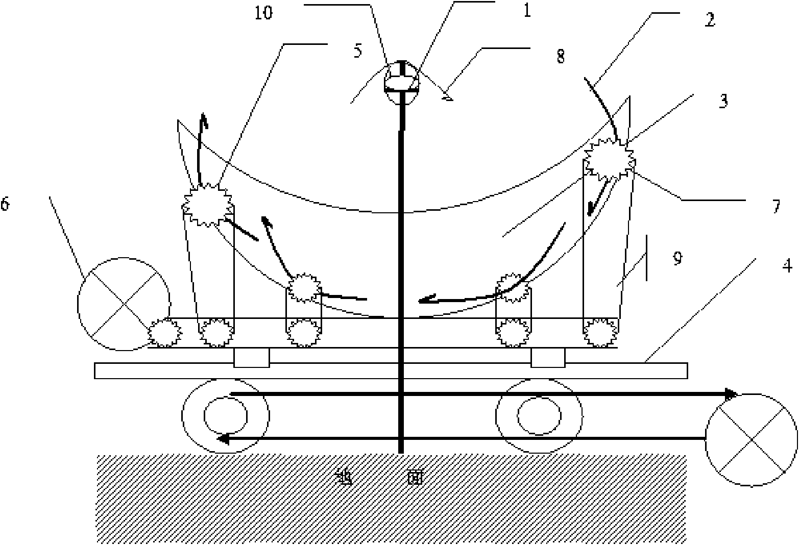
[0058] Two-axis tracking multi-parabolic mirror solar point focusing heat pipe utilization system (side view)

[0059] Book figure 2 It is a side view, and the solar mirror is a group of solar energy utilization systems composed of four parabolic reflectors (2), heat pipe utilization system (1), solar mirror bracket, etc.; the outside of the heat pipe is provided with a vacuum tube to insulate the heat preservation box; on the building and remain stationary; the parabolic mirror is arranged on a parabolic device (3), and a rotating shaft (5) is arranged on each parabolic mirror, and the solar mirror can rotate along the rotating shaft (5). Each solar mirror tracks the solar energy through different movements, and at the same time focuses the solar light onto the heat pipe. The four parabolic mirrors use the same drive system, and the transmission mechanism is a gear set. Different solar mirrors have different numbers of gear teeth, so they can be used Different rotational sp...

Embodiment 3

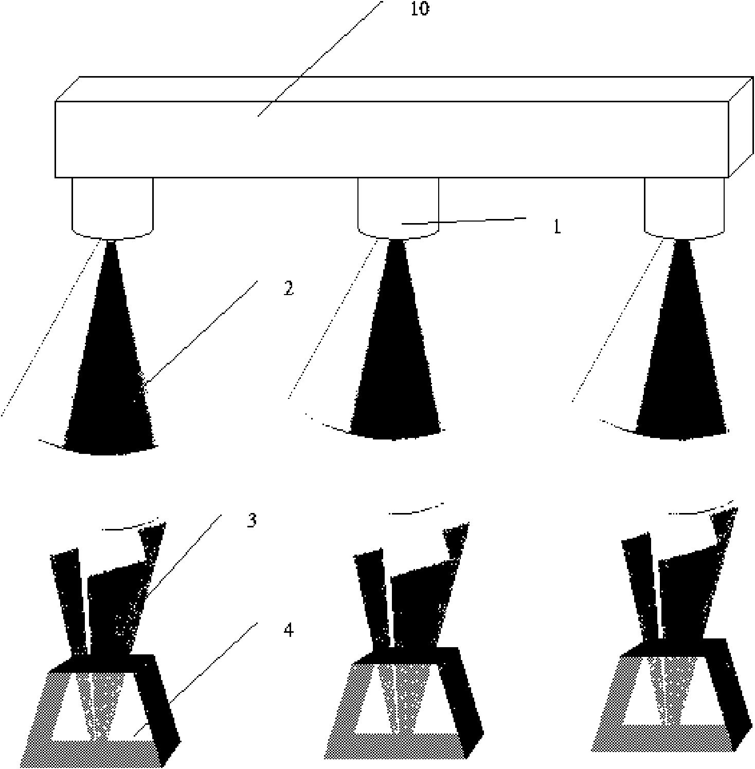
[0060] Embodiment 3. Heat pipe hot spot focused heat pipe utilization system

[0061] Such as image 3 , this case is a solar energy utilization system composed of multiple point-focusing reflectors set on the building, the solar mirror (2) samples point-focused parabolic reflectors, and each point-focused reflector is set on the tracking system (3) , the tracking system is set on the tracking bracket (4), each solar mirror focuses the solar energy on a heat pipe utilization system (1), multiple heat pipes realize the transmission of heat energy through the heat pipe heat transfer system (10), and multiple heat pipe evaporation ends are set The light-to-heat conversion is realized on different point focusing systems, and together they form a whole heat pipe system to realize the transmission and utilization of heat energy. Setting the solar energy utilization of multiple groups in different buildings and ground areas can realize the point-focused utilization of solar energy i...


PUM


Abstract

The invention aims to provide a distributed solar point focusing optical mirror heat pipe tracking and utilizing system, which can be arranged in a distributed manner based on land conditions in urban regions, at least one solar heat pipe system, a solar tracking system, a point focusing solar mirror and a tracking bracket are combined to form a group of solar point focusing utilizing system, multiple groups of solar point focusing utilizing systems are distributed in different areas, and multiple groups of solar heat pipe systems can be mutually connected to jointly form the solar point focusing utilizing system. By changing the array code of the existing trench type solar system into a distributed mode, the trench type solar utilizing technology is led to be applicable to different areas and cities, thus reducing requirements and limitations thereof on field, facilitating integrated applications in different areas and buildings, widening the utilization type and mode of solar energy, and leading various solar energy used thereby available.

Description

technical field [0001] The invention relates to the utilization of solar energy, especially the tracking utilization of solar energy focused on sampling points and its distributed utilization. Background technique [0002] Solar tracking mainly consists of three types: trough type, tower type and butterfly type. Because the trough type system is one-way tracking, the relative technical difficulty is relatively low. At the same time, due to the solar energy selective coating and vacuum tube technology, it has industrial production in the temperature range of 100-400 degrees. Therefore, it can be mass-produced quickly, and the earliest commercial application in the world is the trough system. [0003] The main tracking method of the trough system in the world is to set a heat exchange tube at the focal point of the trough system, fill the heat exchange tube with heat transfer oil or directly heat water into steam, and the motor drives the heat transfer oil or steam to flow In...

Claims


Application Information

Patent Timeline
Patent Type & Authority Applications(China)
IPC IPC(8): F24J2/38F24J2/46F24S10/70F24S10/95F24S50/20
CPCY02B10/20Y02E10/47Y02E10/44
Inventor 李建民
Owner BEIJING WISWORD HI TECH
Why Eureka
Try Eureka