Heat pump installation

A heat pump device and hot water technology, which is applied in the field of heat pump devices, can solve the problems of large heat exchanger load, no other functions, and low utilization efficiency, and achieve the effects of saving operating costs, speeding up, and improving energy efficiency coefficients

Inactive Publication Date: 2008-04-16
PANASONIC CORP
View PDF1 Cites 10 Cited by
  • Summary
  • Abstract
  • Description
  • Claims
  • Application Information

AI Technical Summary

Problems solved by technology

[0003] However, in this air conditioner, the hot water generating device can only be used to generate hot water without other functions, and its size needs to meet the maximum load required for supplying hot water, and the air conditioner water heat exchanger can only be used to Produce air-conditioning water without other uses, and its size needs to meet the maximum

Method used


Image

  • Heat pump installation
  • Heat pump installation
  • Heat pump installation

Examples


no. 1 approach

[0031] A heat pump device as a first embodiment of the present invention will be described in detail below with reference to FIGS. 1 , 2 , 3 and 4 .

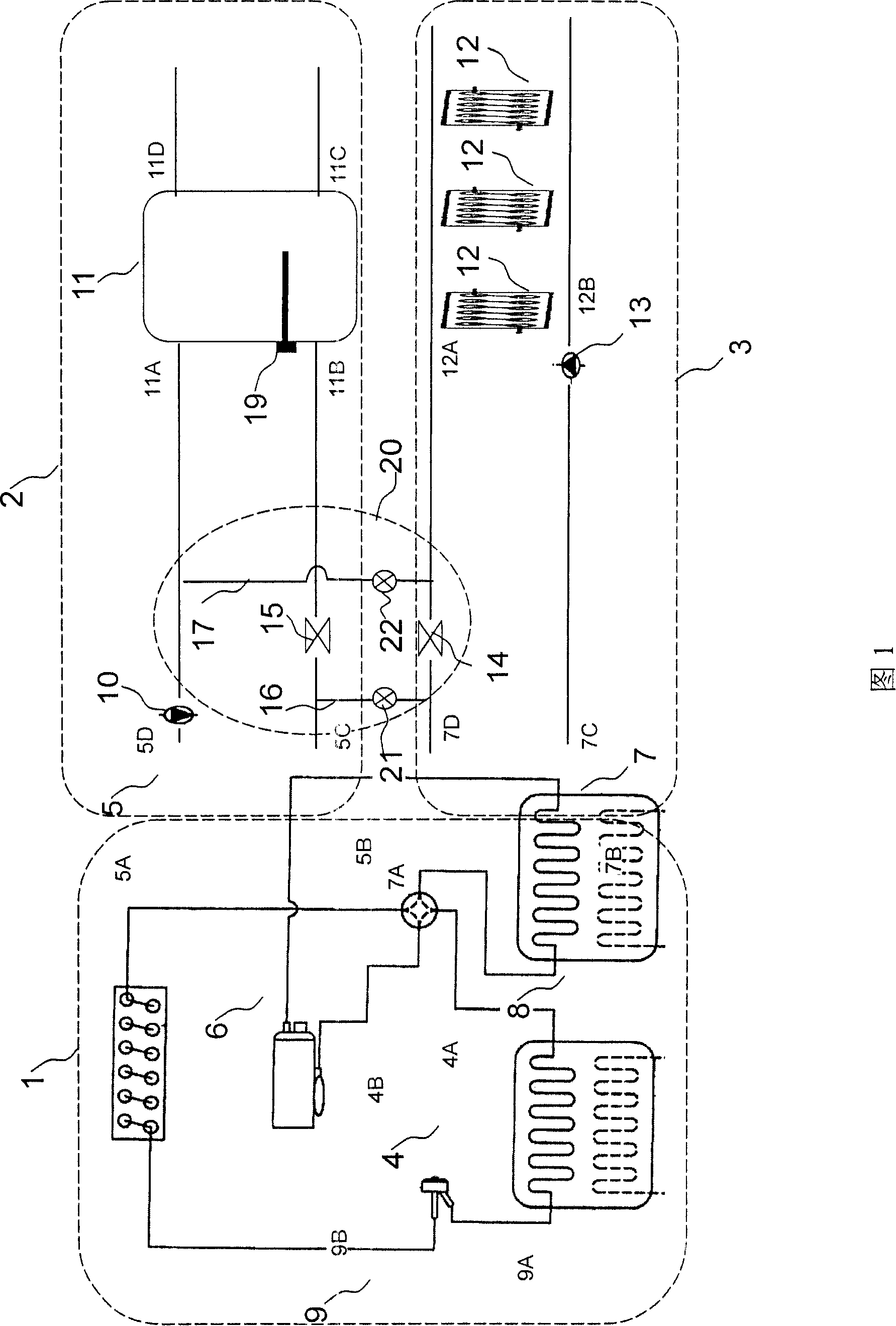
[0032] FIG. 1 is a schematic configuration diagram of a heat pump device according to a first embodiment of the present invention. As shown in FIG. 1 , the heat pump device includes a refrigerant flow path 1 , a hot water flow path 2 , an air conditioning water flow path 3 , and a switchable channel 20 connected between the hot water flow path 2 and the air conditioning water flow path 3 . The refrigerant flow path 1 includes: a compressor 4 that compresses refrigerant to generate high-temperature and high-pressure refrigerant, a hot water heat exchanger 5 that transfers heat between the high-temperature refrigerant and water to generate hot water, a four-way valve 6, An air-conditioning water heat exchanger 7 that transfers heat between refrigerant and air-conditioning water to generate air-conditioning hot water or air-conditi...

no. 2 approach

[0056] A heat pump device as a second embodiment of the present invention will be described in detail below with reference to FIGS. 5 to 7 .

[0057] Fig. 5 is a schematic configuration diagram showing a heat pump device according to a second embodiment of the present invention. As shown in FIG. 5 , the heat pump device includes a refrigerant flow path 1 , a hot water flow path 2 , an air-conditioning water flow path 3 , and a switchable channel 30 connected between the hot water flow path 2 and the air-conditioning water flow path 3 . Wherein, except for the switch-controllable channel 30, other devices and their connections are the same as those in the first embodiment.

[0058] The switchable channel 30 includes the first switchable channel 16 and the second switchable channel 18 . The first switch-controllable channel 16 is connected between the pipeline connecting the hot water heat exchanger 5 and the valve 15 and the pipeline connecting the air-conditioning water heat ...

no. 3 approach

[0075] A heat pump device according to a third embodiment of the present invention will be described in detail below with reference to FIGS. 8 to 12 .

[0076] Fig. 8 is a schematic configuration diagram showing a heat pump device according to a third embodiment of the present invention. As shown in FIG. 8 , the heat pump device includes a refrigerant flow path 1 , a hot water flow path 2 , an air-conditioning water flow path 3 , and a switchable channel 40 connected between the hot water flow path 2 and the air-conditioning water flow path 3 . Wherein, except for the switch-controllable channel 40, the others are the same as the first embodiment.

[0077] The switch-controllable channel 40 includes the first switch-controllable channel 16 , the second switch-controllable channel 17 and the third switch-controllable channel 18 . The first switch-controllable channel 16 is connected between the pipeline connecting the hot water heat exchanger 5 and the valve 15 and the pipelin...


PUM


Abstract

A heat pump unit comprises a refrigerating fluid stream, a hot water stream, an air conditioning water stream and a switch controllable channel. The invention is characterized in that the refrigerating fluid stream comprises a compressor, a hot water heat exchanger, an air conditioning water heat exchanger, an outdoor heat exchanger, a four-way valve and a decompressor; the hot water stream comprises a hot water heat exchanger, a hot water stream recycle pump, a water tank for storing hot water and a first valve connected between the hot water heat exchanger and the water tank; the air conditioning water stream comprises an air conditioning water heat exchanger, an air conditioning water recycle pump, an indoor heat exchanger for transmitting heat energy between the air conditioning water and the indoor air, and a second valve connected between the air conditioning water heat exchanger and an indoor heat exchanger; the switch controllable channel is connected between the hot water stream and the air conditioning water stream. The heat pump of the invention can simultaneously utilize both the hot water heat exchanger and the air conditioning water heat exchanger to produce water for the air conditioner, which increases the ratio of the performance of system to cost.

Description

technical field [0001] The present invention relates to heat pump devices. Background technique [0002] In the prior art, there is disclosed an air conditioner that can simultaneously heat / cool and provide hot water, which includes: a compressor that compresses refrigerant to generate high-temperature gaseous refrigerant, and a compressor that passes through water and water from the compressor A hot water generating device that generates hot water through a heat exchange process that transfers heat between refrigerants at high temperatures, an outdoor heat exchanger that generates hot water through a heat exchange process that transfers heat between refrigerant and outdoor air, and an outdoor heat exchanger that passes between water and A hot water generating device that generates hot water by a heat exchange process that transfers heat between refrigerants, or a hot / cold water generating device that generates cold water by transferring heat between water and refrigerant fr...

Claims


Application Information

Patent Timeline
IPC IPC(8): F25B29/00F24D17/02
Inventor 冯伟章
Owner PANASONIC CORP
Why Eureka
Try Eureka