Conveying line for alternately conveying workpieces

A conveyor line and workpiece technology, applied in the direction of conveyor objects, transportation and packaging, etc., can solve the problems of reduced production efficiency, high manufacturing costs, and pipeline jams, and meet the requirements of reduced accuracy, high-precision centering, The effect of improving supply efficiency

Inactive Publication Date: 2017-12-01
广州市康超信息科技有限公司
View PDF0 Cites 6 Cited by
  • Summary
  • Abstract
  • Description
  • Claims
  • Application Information

AI Technical Summary

Problems solved by technology

A single conveyor belt is common in the prior art, and this structure needs to process the workpiece before the next workpiece can be processed, which leads to too long idle time between the various mechanisms, and a long time for the finished product of the assembly line, which cannot increase the production capacity
There are still some alternate transfer methods in the prior art that use manual or special mechanical arms to realize the alternate feeding of these objects, but the manual production efficiency is low and is easily affected by the operator’s subjective factors; There are advantages, but the manufacturing cost is very expensive, the use environment requirements are relatively harsh, and it is not easy to maintain
Moreover, in the process of conveying, due to the effects of inertia and friction, the forward direction of the object is inconsistent, especially for objects on a large conveying line, when the object is not accurately aligned on the subsequent conveying line, due to Objects do not have a precise relative positional relationship. If the object has a large deviation from the preset position in the subsequent process, it will cause the assembly line to freeze. The subsequent processing quality is not high, and high-precision effects cannot be achieved, which reduces production efficiency.

Method used


Image

  • Conveying line for alternately conveying workpieces
  • Conveying line for alternately conveying workpieces
  • Conveying line for alternately conveying workpieces

Examples


Embodiment Construction

[0021] The present invention will be further described in detail below in conjunction with the embodiments and the accompanying drawings, but the embodiments of the present invention are not limited thereto.

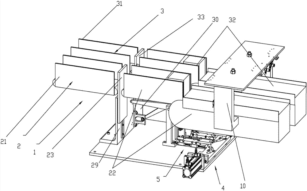
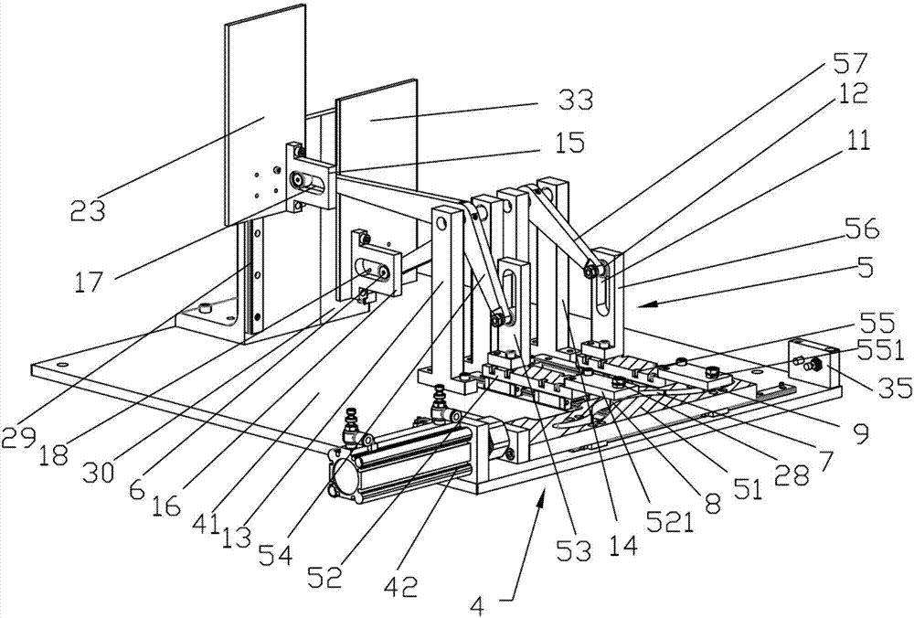
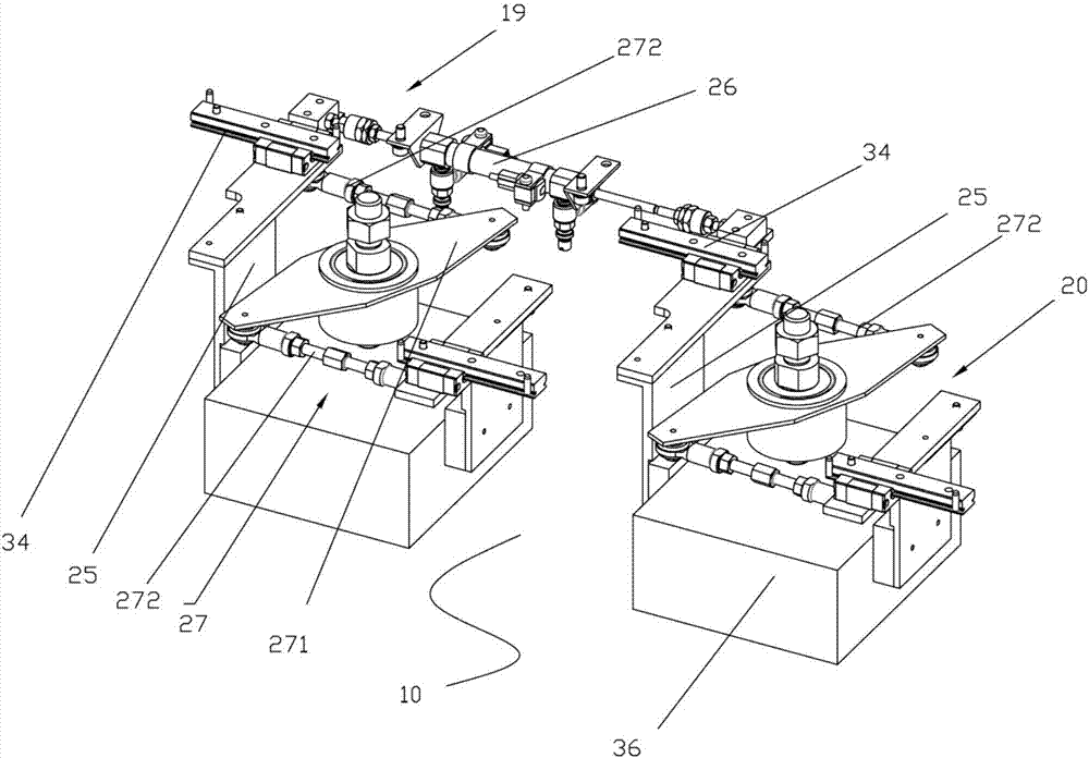
[0022] like figure 1 A conveying line for alternately conveying workpieces is shown, including a conveying mechanism 1 and a centering mechanism 10. The conveying mechanism 1 includes a left conveyor belt group 2 and a right conveyor belt group 3 arranged side by side, and the left conveyor belt group 2 includes front and back arranged The left front conveyor belt 21, the left rear conveyor belt 22 and the liftable left lifting baffle 23 arranged between the left rear conveyor belt 21 and the left front conveyor belt 22, the right conveyor belt group 3 includes the right front conveyor belt 31, the right rear conveyor belt 32 and the rear conveyor belt 32 arranged front and back. The liftable right lifting baffle 33 that is arranged between the right front conveyor belt ...


PUM


Abstract

The invention discloses a conveying line for conveying workpieces alternately, comprising a conveying mechanism and a centering mechanism. The conveying mechanism includes a left conveyor belt group and a right conveyor belt group distributed side by side; the centering mechanism includes a left conveyor belt set on the left rear conveyor belt. The centering mechanism and the right centering mechanism arranged on the right rear conveyor belt, the left centering mechanism and the right centering mechanism both include a fixing frame, two gripping hands slidably connected with the fixing frame and in opposite directions of travel, and a driving gripping hand Linear motion cylinder; the left and right conveyor belt groups are respectively provided with left and right lifting baffles that can be raised and lowered, and the left and right lifting baffles are alternately raised and blocked to realize the alternate transportation of workpieces, and through the centering mechanism The mutual movement of the two grippers clamps the workpiece, realizes the correction of the position and angle of the workpiece, and improves the accuracy of conveying the workpiece.

Description

technical field [0001] The invention relates to the technical field of conveying and assembling, in particular to a conveying line for alternately conveying workpieces. Background technique [0002] At present, in industrial production, it is often necessary to alternately carry out follow-up processing on the objects on the conveying line. In this case, it is necessary to alternately load the objects on different conveying lines. A single conveyor belt is common in the prior art, and this structure needs to process the workpiece before the next workpiece can be processed, which leads to too long idle time between the various mechanisms and the long time for the finished product of the assembly line, which cannot increase the production capacity . There are still some alternate transfer methods in the prior art that use manual or special mechanical arms to realize the alternate feeding of these objects, but the manual production efficiency is low and is easily affected by t...

Claims


Application Information

Patent Timeline
Patent Type & Authority Applications(China)
IPC IPC(8): B65G47/88B65G47/52B65G47/24B65G47/90
CPCB65G47/8884B65G47/24B65G47/52B65G47/90
Inventor 孟青李良浩
Owner 广州市康超信息科技有限公司
Why Eureka
Try Eureka