Supercharge Your Innovation With Domain-Expert AI Agents!

Ultrasound diagnostic apparatus and ultrasound diagnostic image data processing method

a diagnostic apparatus and ultrasound technology, applied in ultrasonic/sonic/infrasonic image/data processing, instruments, tomography, etc., can solve the problems of reducing the brightness of the image, affecting the quality of the element data obtained by processing the reception signal, and difficulty in adjusting to an optimal focus

Inactive Publication Date: 2018-12-04
FUJIFILM CORP
View PDF9 Cites 0 Cited by
  • Summary
  • Abstract
  • Description
  • Claims
  • Application Information

AI Technical Summary

Benefits of technology

[0009]To attain the above objects, a first embodiment of the present invention provides an ultrasound diagnostic apparatus, comprising: an ultrasound transmitting / receiving unit which transmits ultrasonic pulses to a subject by using a plurality of ultrasound transmitting / receiving elements arranged in one direction, and receives an ultrasonic echo that is the ultrasonic pulse reflected by the subject, to produce element data; an element data storing unit which stores the element data produced by the ultrasound transmitting / receiving unit; a delay correction unit which corrects a delay time of the plurality of ultrasound transmitting / receiving elements in an arranging direction thereof by using a predetermined sonic speed setting value, to perform phasing on the element data, the delay time being an arrival time difference of the ultrasonic echo in the element data read out from the element data storing unit; an element data determining unit which determines the quality of the element data, based on the element data after correction of the delay time of the plurality of ultrasound transmitting / receiving elements in the arranging direction thereof, the quality of the element data being susceptible to a noise in the element data; and an image producing unit which produces an ultrasound image, by performing different processes on the element data in response to a determination result from the element data determining unit.

Problems solved by technology

However, in JP 2009-142680 A, even if a plurality of setting values are prepared, there is a problem in that, it is difficult to adjust to an optimum focus, because if the quality of the reception signal processed in an ultrasound transmitting / receiving unit 2 is degraded due to much noise, the quality of the element data obtained by processing the reception signal is also degraded, and brightness is degraded by performing phasing addition on the partially or entirely phase-shifted element data.

Method used


Image

  • Ultrasound diagnostic apparatus and ultrasound diagnostic image data processing method
  • Ultrasound diagnostic apparatus and ultrasound diagnostic image data processing method
  • Ultrasound diagnostic apparatus and ultrasound diagnostic image data processing method

Examples


embodiment 1

[0067]First, Embodiment 1 of the ultrasound diagnostic apparatus according to the present invention will be described.

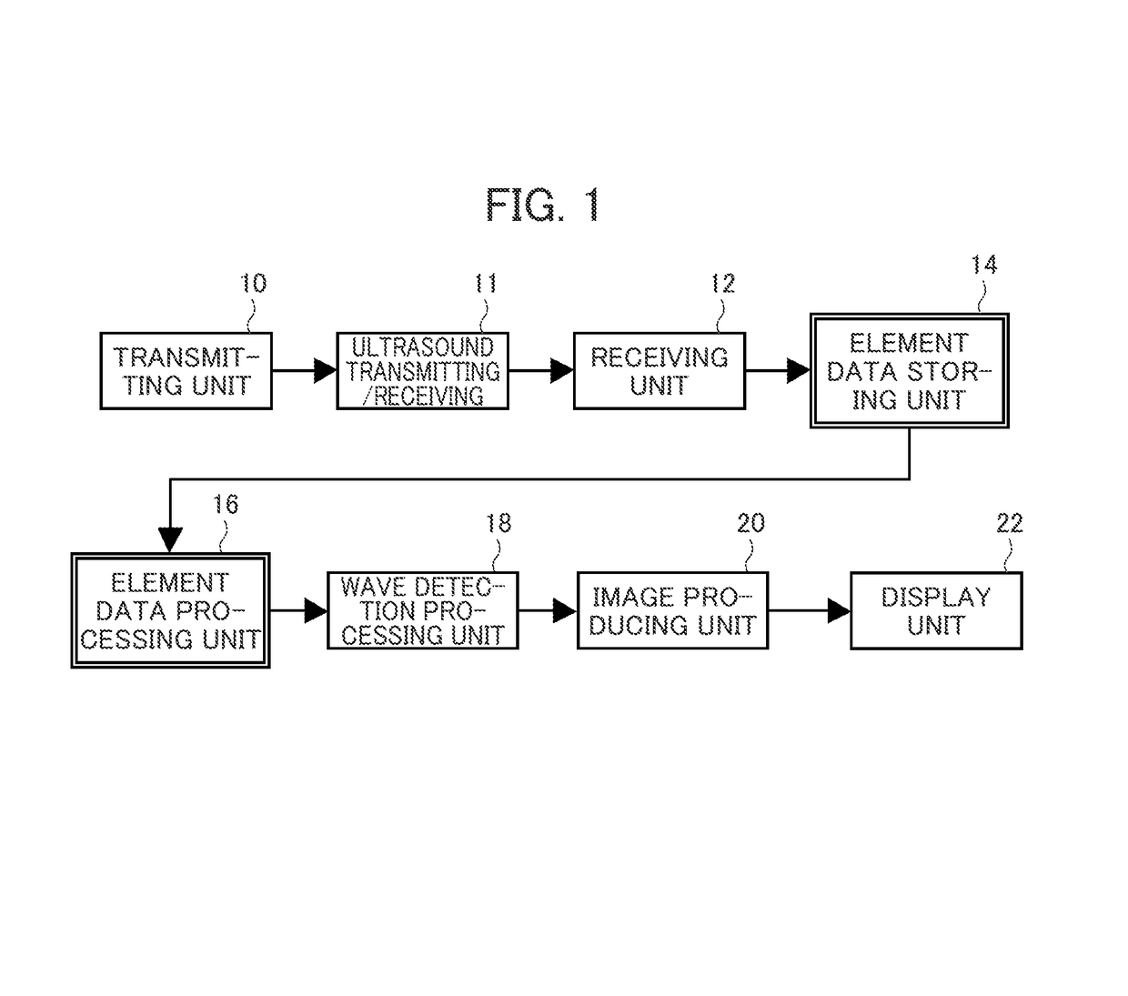
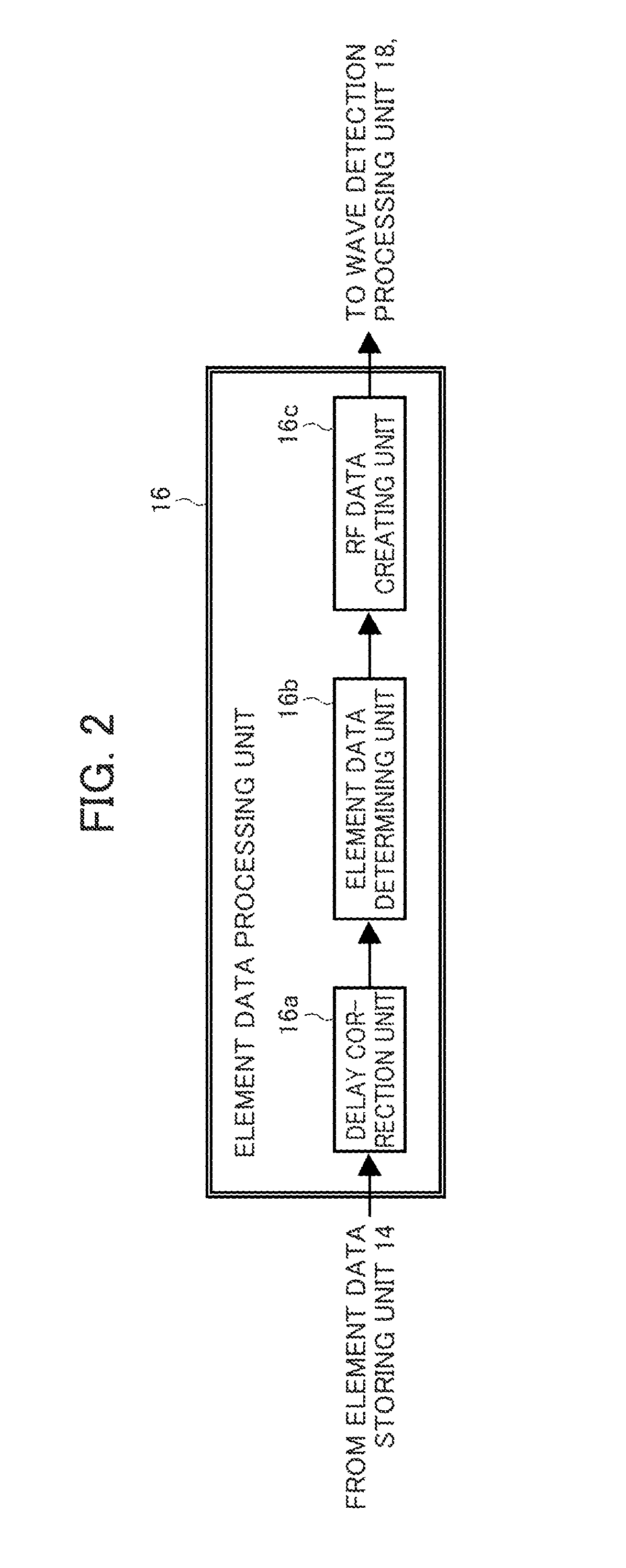
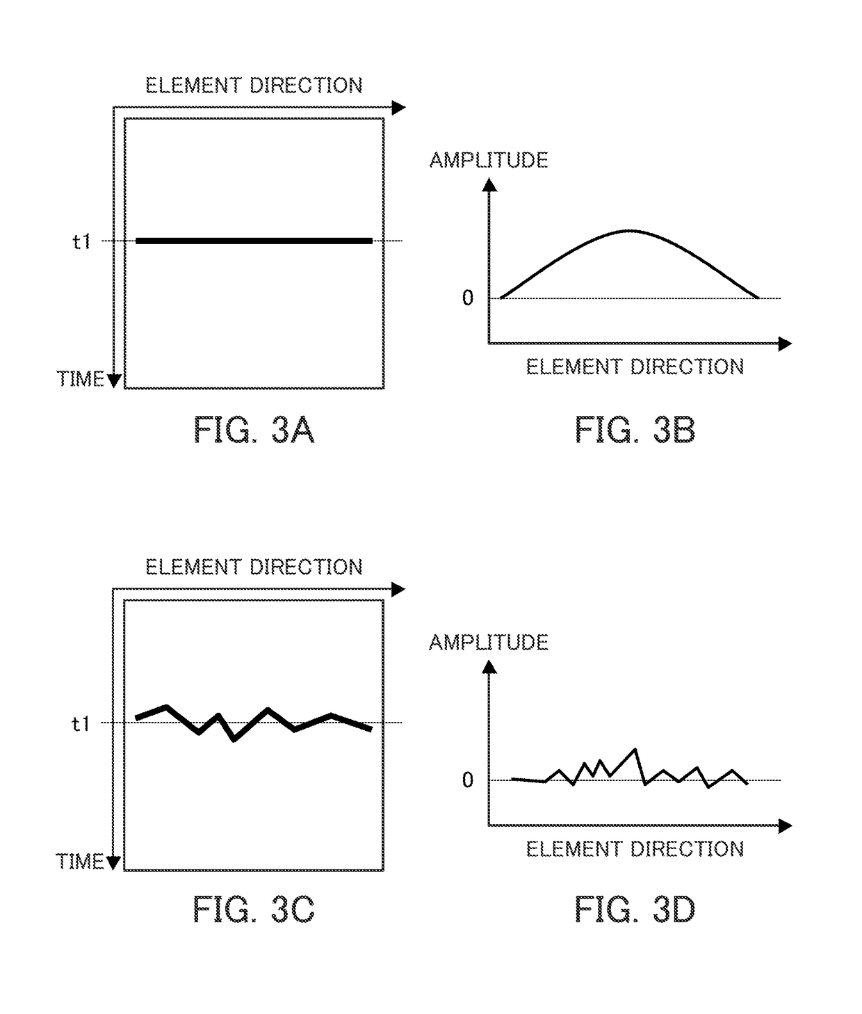
[0068]FIG. 5 is a functional block diagram showing Embodiment 1 of the ultrasound diagnostic apparatus shown in FIGS. 1 and 2. FIG. 6A is an explanatory diagram illustrating a process content for the high quality element data with low noise, and FIG. 6B is an explanatory diagram illustrating a process content for the low quality element data to which delay correction did not function properly due to influence of the noise. Embodiment 1 shows the process content in respective components of the element data processing unit 16 shown in FIG. 2, in more detail.

[0069]Other parts are the same as the embodiment of the ultrasound diagnostic apparatus according to the present invention shown in FIG. 1.

[0070]A delay correction unit 160 corresponds to the delay correction unit 16a in FIG. 2, and performs delay correction to the element data stored in the element data storing uni...

embodiment 2

[0087]Next, Embodiment 2 of the ultrasound diagnostic apparatus according to the present invention will be described.

[0088]FIG. 8 is a functional block diagram showing Embodiment 2 of the ultrasound diagnostic apparatus shown in FIGS. 1 and 2. Embodiment 2 additionally includes an image quality determining unit 21 between the image producing unit 20 and the display unit 22 in the functional block diagram showing Embodiment 1 of the ultrasound diagnostic apparatus shown in FIG. 5. If the determination result is “OK”, the process proceeds to the display unit 22 same as in Embodiment 1. If the determination result shows “NG”, the process returns to the delay correction unit 160 in Embodiment 1 through the process condition changing unit 24.

[0089]Other parts are the same as Embodiment 1 of the procedure of the process method of the ultrasound diagnostic apparatus, shown in FIG. 5.

[0090]The image quality determining unit 21 determines whether the image quality of the B-mode image data cr...


PUM


Abstract

In this ultrasound diagnostic device and ultrasound diagnostic image data processing method, an element data determination unit compares a pre-set threshold value with the average value of the amplitude values in the element direction of the element data calculated by an average value calculation unit in the element direction, and an RF data calculation unit performs a process in which the element data of which the absolute value of the amplitude value is the maximum is adopted as the RF data without phasing addition when the average value (Aa) is greater than the threshold value. Meanwhile, when the average value (Ab) is equal to or lower than the threshold value, the RF data calculation unit performs a process in which the average values of all the amplitude values in the element direction of the element data are adopted as the RF data without phasing addition.

Description

CROSS-REFERENCE TO RELATED APPLICATIONS[0001]This application is a Continuation of PCT International Application No. PCT / JP2013 / 064460 filed on May 24, 2013, which claims priority under 35 U.S.C. § 119(a) to Japanese Application No. 2012-120010 filed on May 25, 2012. Each of the above application(s) is hereby expressly incorporated by reference, in its entirety, into the present application.BACKGROUND OF THE INVENTION[0002]The present invention relates to an ultrasound diagnostic apparatus and an ultrasound diagnostic image data processing method, and in particular, to an ultrasound diagnostic apparatus and an ultrasound diagnostic image data processing method for photographing and displaying an ultrasound image of a subject by using an ultrasonic wave.[0003]In the field of medicine, ultrasound diagnostic apparatuses are widely used for diagnostics and inspections. An ultrasound diagnostic apparatus irradiates an ultrasonic wave to a subject through an ultrasound probe and produces ...

Claims


Application Information

Patent Timeline
Patent Type & Authority Patents(United States)
IPC IPC(8): A61B8/08A61B8/14G01S7/52G01S15/89A61B8/00
CPCA61B8/5269A61B8/14A61B8/4488G01S7/52049G01S15/8915A61B8/5207A61B8/58
Inventor YAMAMOTO, HIROAKI
Owner FUJIFILM CORP
Features
  • R&D
  • Intellectual Property
  • Life Sciences
  • Materials
  • Tech Scout
  • Unparalleled Data Quality
  • Higher Quality Content
  • 60% Fewer Hallucinations
Learn More