Adjustable stroke mechanism for random orbital machine
a random orbital machine and stroke mechanism technology, which is applied in the direction of grinding drives, cranks, manufacturing tools, etc., can solve the problems of not being able to remove surface defects, requiring more skill and control of the machine than a typical hobbyist, and scratch removal
- Summary
- Abstract
- Description
- Claims
- Application Information
AI Technical Summary
Benefits of technology
Problems solved by technology
Method used
Image
Examples
first embodiment
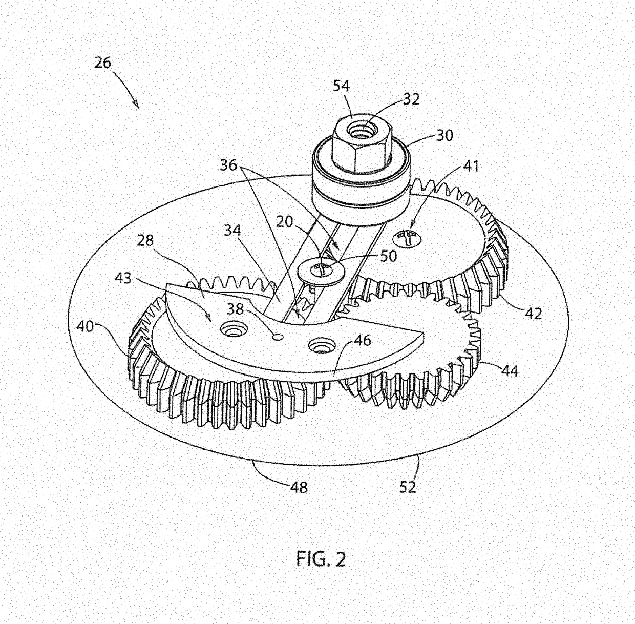
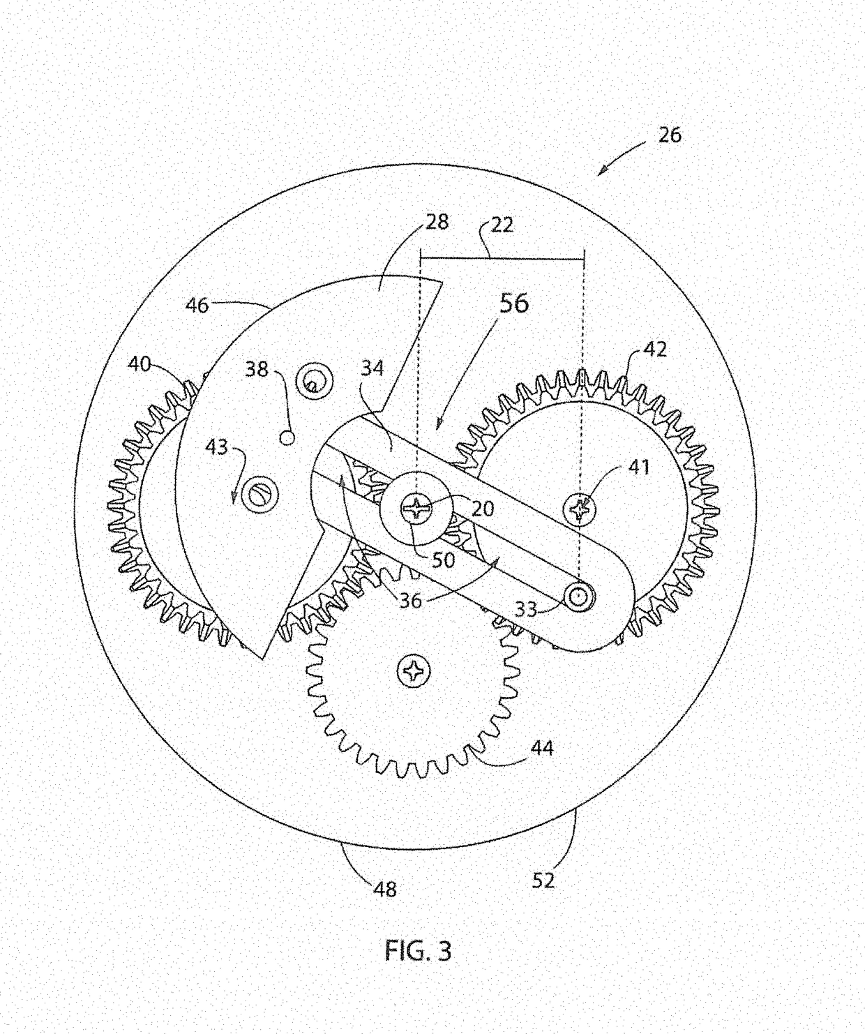
[0056]Moving on to FIG. 2, an adjustable stroke mechanism 26 is shown. The adjustable stroke mechanism 26 utilizes a series of gears to allow the backing plate mount 54 and counterweight 28 to automatically move toward or away from one another as any one of the gears is rotated. These synched movements of the backing plate mount 54 and the counterweight 28 allow the offset, or stroke, of a random orbital machine 10 to be adjusted while keeping vibrations in check. The offset may be adjusted between a maximum and minimum setting, or be adjustable by choosing a series of pre-selected settings.
[0057]A shroud will enclose the adjustable stroke mechanism 26 and is represented by a proposed shroud perimeter 48. The shroud would function much as the shroud 12 shown in FIG. 1 and will enclose the components of the adjustable stroke mechanism 26. The proposed shroud curvature 52 may also be matched to the counterweight curvature 46 such that the counterweight 28 will not intersect the propos...
second embodiment
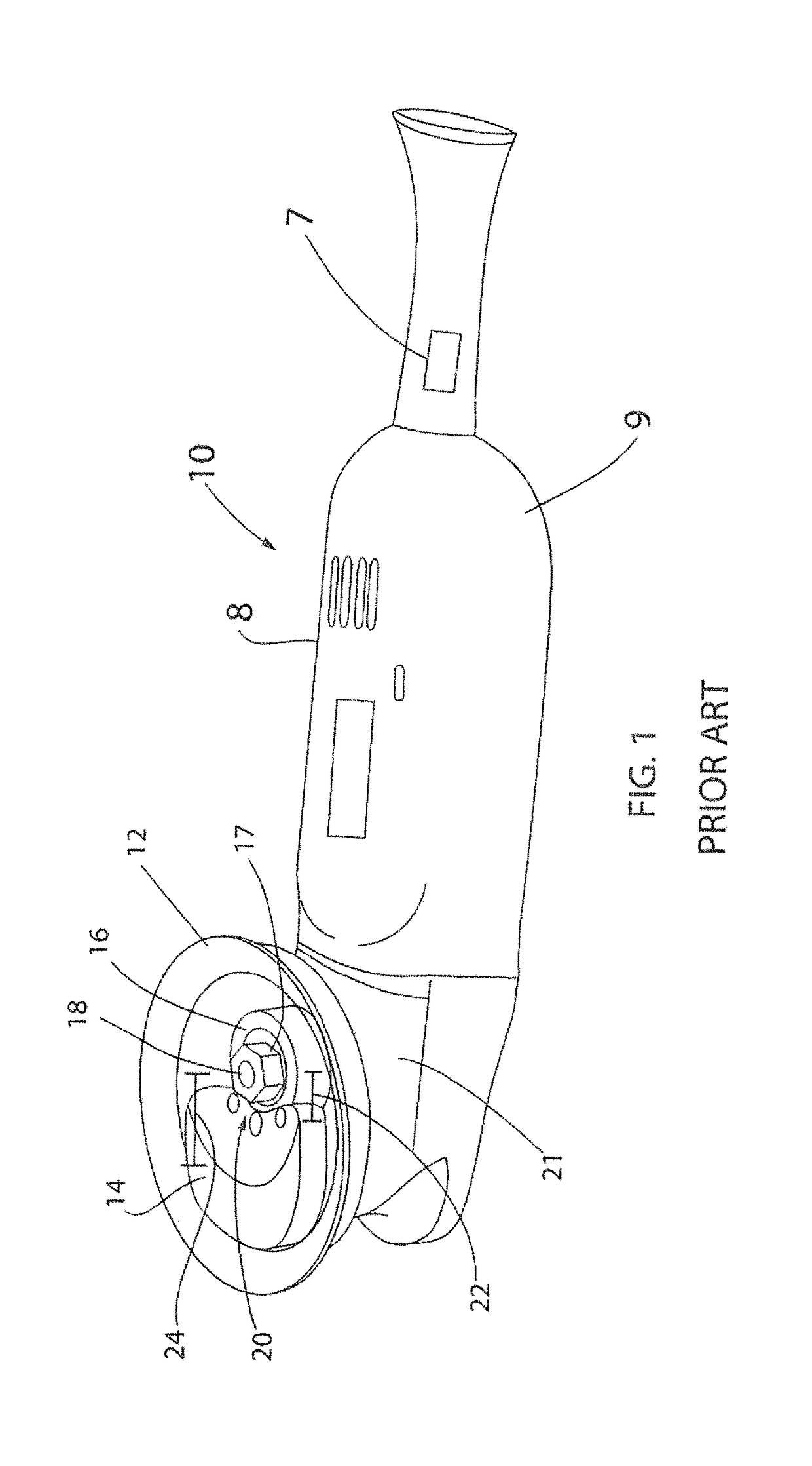
[0065]Transitioning now to FIG. 6, an adjustable stroke mechanism 60 is shown. The adjustable stroke mechanism 60 is represented within the perimeter of a shroud 48, similar to the known random orbital machine 10 in FIG. 1. The proposed shroud perimeter 48 also has a proposed shroud curvature 52 that houses the entire adjustable stroke mechanism 60. The entire adjustable stroke mechanism 60 rotates within the proposed shroud perimeter 48 when the random orbital machine 10 is activated by depressing the switch 7.
[0066]A fully extended stroke 74 is shown in FIG. 6. The stroke radius 22 is shown by the offset of the backing plate mount 54 to the rotational axis 20 of the backing plate mount 54. The counterweight 28 balances out the backing plate mount 54 such that minimal vibrations are experienced when the adjustable stroke mechanism 60 is activated.
[0067]The stroke radius 22 is adjusted by movement of a first rack gear 66, a second rack gear 68, a first pinion gear 62, and a second p...
third embodiment
[0070]Referring now to FIG. 8, an adjustable stroke mechanism 100 is shown in an exploded perspective view in order to show the various components within the adjustable stroke mechanism 100. The adjustable stroke mechanism 100 includes a housing 102 having a wall 104 surrounding a cavity 106. As shown in FIG. 8, the wall 104 is depicted as circular in shape; however, the wall 104 could be in the form of any number of shapes. In addition, the housing 102 includes a top plate 108 oriented perpendicular to the wall 104, which provides an upper limit to the cavity 106. The housing 102 also includes a housing cover 110 oriented perpendicular to the wall 104 and opposite the top plate 108, which provides a lower limit to the cavity 106. The wall 104 of the housing 102 has a plurality of apertures 112 formed therein. While FIG. 8 shows two (2) apertures 112 formed in the wall 104, it is contemplated that either more or less than two (2) apertures 112 may be formed in the wall 104.
[0071]An ...
PUM
| Property | Measurement | Unit |
|---|---|---|
| time | aaaaa | aaaaa |
| pressure | aaaaa | aaaaa |
| stroke diameter | aaaaa | aaaaa |
Abstract
Description
Claims
Application Information
 - R&D
- Intellectual Property
- Life Sciences
- Materials
- Tech Scout
- Unparalleled Data Quality
- Higher Quality Content
- 60% Fewer Hallucinations
Browse by: Latest US Patents, China's latest patents, Technical Efficacy Thesaurus, Application Domain, Technology Topic, Popular Technical Reports.
© 2025 PatSnap. All rights reserved.Legal|Privacy policy|Modern Slavery Act Transparency Statement|Sitemap|About US| Contact US: help@patsnap.com


