Coil spring

a coil spring and coil spring technology, applied in the field of coil springs, can solve the problems of difficult production and unsatisfactory coil springs 100 b>

Active Publication Date: 2018-12-04
NHK SPRING CO LTD
View PDF21 Cites 4 Cited by
  • Summary
  • Abstract
  • Description
  • Claims
  • Application Information

AI Technical Summary

Benefits of technology

[0010]According to the coil spring of the present embodiment, in a state in which the coil spring is compressed to the specified height, the effective portion does not have bowing. Accordingly, in a state in which the coil spring is incorporated into a suspension of a vehicle, for example, the coil spring can be prevented from interfering with the surrounding components. Moreover, the coil spring of the present embodiment can be produced by a hot forming coiling machine. The coil spring can be used in, for example, a link-motion-type suspension, not limited to a strut-type suspension. Also, the coil spring of the present embodiment can be used in an application other than a suspension.

Problems solved by technology

The coil spring 100 having the bowing may interfere with the surrounding components, and thus, such coil spring 100 is not desirable.
Since it is sometimes difficult to actually produce a coil spring of such a special shape by a hot forming coiling machine, the cold forming coiling machine is used.

Method used


Image

  • Coil spring
  • Coil spring
  • Coil spring

Examples


Embodiment Construction

[0027]A coil spring according to one embodiment of the present invention will now be described with reference to FIGS. 1 to 9.

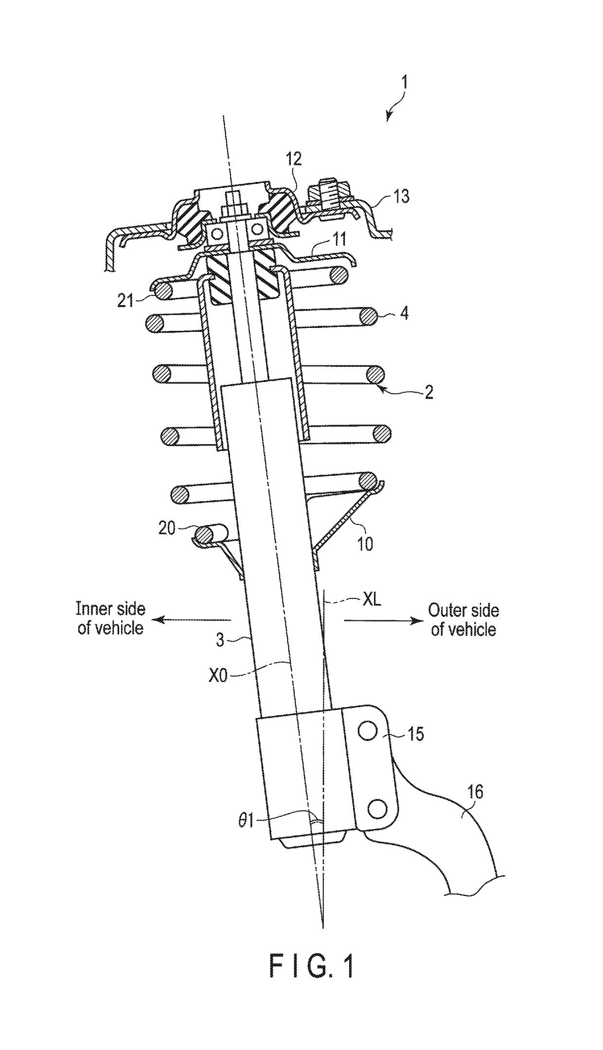
[0028]A McPherson-strut-type suspension 1 shown in FIG. 1 comprises a suspension coil spring 2 (hereinafter simply referred to as a coil spring 2), and a strut 3 formed of a shock absorber. The coil spring 2 comprises a wire 4 made of spring steel which is formed into a helical shape. The coil spring 2 is mounted in the suspension 1 in a state in which it is compressed between a lower spring seat 10 and an upper spring seat 11. An upper end of the strut 3 is mounted on a vehicle body 13 via a mount insulator 12. A bracket 15 is provided at the lower part the strut 3. A knuckle member 16 (only a part of which is shown) for supporting an axle is mounted on the bracket 15. The strut 3 is mounted in the vehicle body 13 in such a state that an upper end side of the strut 3 is inclined, more specifically, axis X0 is inclined toward the inner side of the vehicle at ...


PUM


Abstract

A coil spring according to one embodiment includes a lower end turn portion which is in contact with a lower spring seat, an upper end turn portion which is in contact with an upper spring seat, and an effective portion between the lower end turn portion and the upper end turn portion. The coil spring is cylindrical about an axis of the effective portion in its free shape which is not compressed. Further, with respect to a coordinate system in which a force line is assumed as a Z-axis, the coil spring is cylindrical with a constant pitch in a direction along the Z-axis in its compressed shape which is compressed to a specified height.

Description

BACKGROUND OF THE INVENTION[0001]1. Field of the Invention[0002]The present invention relates to a coil spring which can be used in a suspension of a vehicle, for example.[0003]2. Description of the Related Art[0004]As a method of producing a coil spring, a method of forming the coil spring by hot working and a method of forming the coil spring by cold working are known. The coil spring formed by hot working is formed into a helical shape by winding a wire that is heated to a high temperature (for example, an austenitizing temperature of steel) around a mandrel at a predetermined pitch. The length of the wire is equivalent to that of one coil spring. In this specification, an apparatus which produces a coil spring by hot working is referred to as a hot forming coiling machine, and the coil spring formed by hot working is referred to as a hot formed coil spring. Since the hot forming coiling machine winds a wire which has been softened as a result of heating around the mandrel, it is...

Claims


Application Information

Patent Timeline
Patent Type & Authority Patents(United States)
IPC IPC(8): B60G11/14F16F1/12
CPCB60G11/14F16F1/123F16F2232/08B60G2206/426B60G2206/81035B60G2202/312B60G15/063B60G2204/1242F16F1/08F16F2226/04F16F1/06B60G2202/12B60G11/16F16F9/58F16F9/54
Inventor NISHIZAWA, SHINICHI
Owner NHK SPRING CO LTD
Why Eureka
Try Eureka