Digital phase locked loop and method for correcting interference components in a phase locked loop

a phase lock and interference technology, applied in the direction of phase difference detection of angle demodulation, automatic control of pulses, electrical equipment, etc., can solve the problems of affecting transmission quality and impeded desire for easy portability

Inactive Publication Date: 2006-12-14
INTEL CORP
View PDF13 Cites 2 Cited by
  • Summary
  • Abstract
  • Description
  • Claims
  • Application Information

AI Technical Summary

Benefits of technology

[0008] The invention is directed to a digital phase locked loop in which the interference components in the output signal are reduced. The invention is also directed to a method for correcting a phase locked loop by means of which the interference signals can be reduced.
[0011] By means of this exemplary configuration, a correction signal is generated in a manner dependent on the word derived from the second frequency word, the value of the correction signal increasing with each step by the value of the derived word. In a suitable embodiment, the summation unit contains an overflow output that can be used to indicate an overflow, that is to say an amount that exceeds a maximum value. As a result, a periodic correction signal can be generated in a simple manner, the periodicity corresponding to a periodicity of the error component of the integrated word downstream of the integrator.
[0013] With the aid of the control circuit, a possibility is afforded of synchronizing the generation of the correction word with the generation of the error component within the control loop. In other words, the control circuit synchronizes a phase of the error component in the output word of the integrator with a phase of the correction word. In one embodiment, the control circuit is configured to temporally regulate the outputting of the correction word. An optimum suppression of the error component is thereby achieved.
[0016] In one embodiment of the invention, the forward path of the phase locked loop also comprises an adder besides an integrator. The adder is connected upstream of the input of the integrator and has a first input and a second input. The first input is coupled to the first terminal of the correction circuit and the second input is coupled to the second terminal of the correction circuit. In this example, a frequency setting word composed of the first frequency word and the second frequency word is thus advantageously fed to the integrator. This is expedient particularly when the first frequency word represents an integer component and the second frequency word represents a fractional component. The corresponding frequency setting word represents the sum of both. It thus becomes possible for the phase locked loop to generate output signals having a frequency which correspond to a non-integer multiple of a reference frequency.

Problems solved by technology

The desire for easy portability is often impeded by the technology used heretofore, which is essentially based on analog signal processing.
These interference signals mean that the transmission quality is impaired and require complex filter measures to suppress them.

Method used


Image

  • Digital phase locked loop and method for correcting interference components in a phase locked loop
  • Digital phase locked loop and method for correcting interference components in a phase locked loop
  • Digital phase locked loop and method for correcting interference components in a phase locked loop

Examples


Embodiment Construction

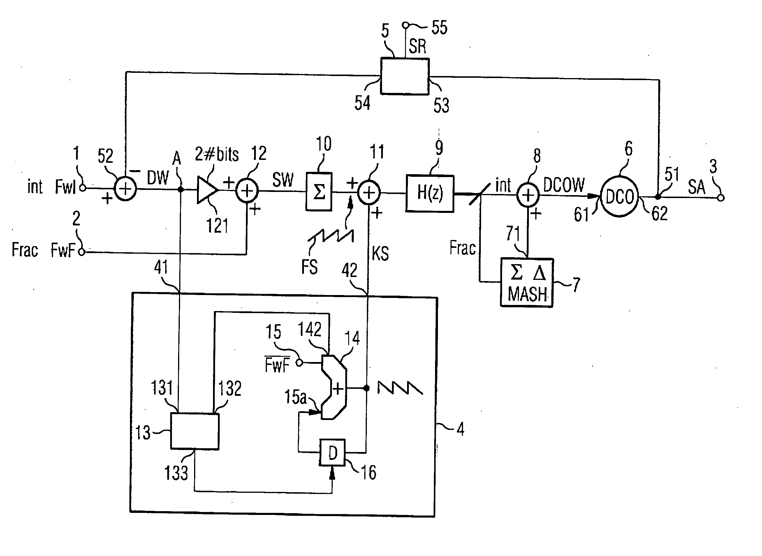
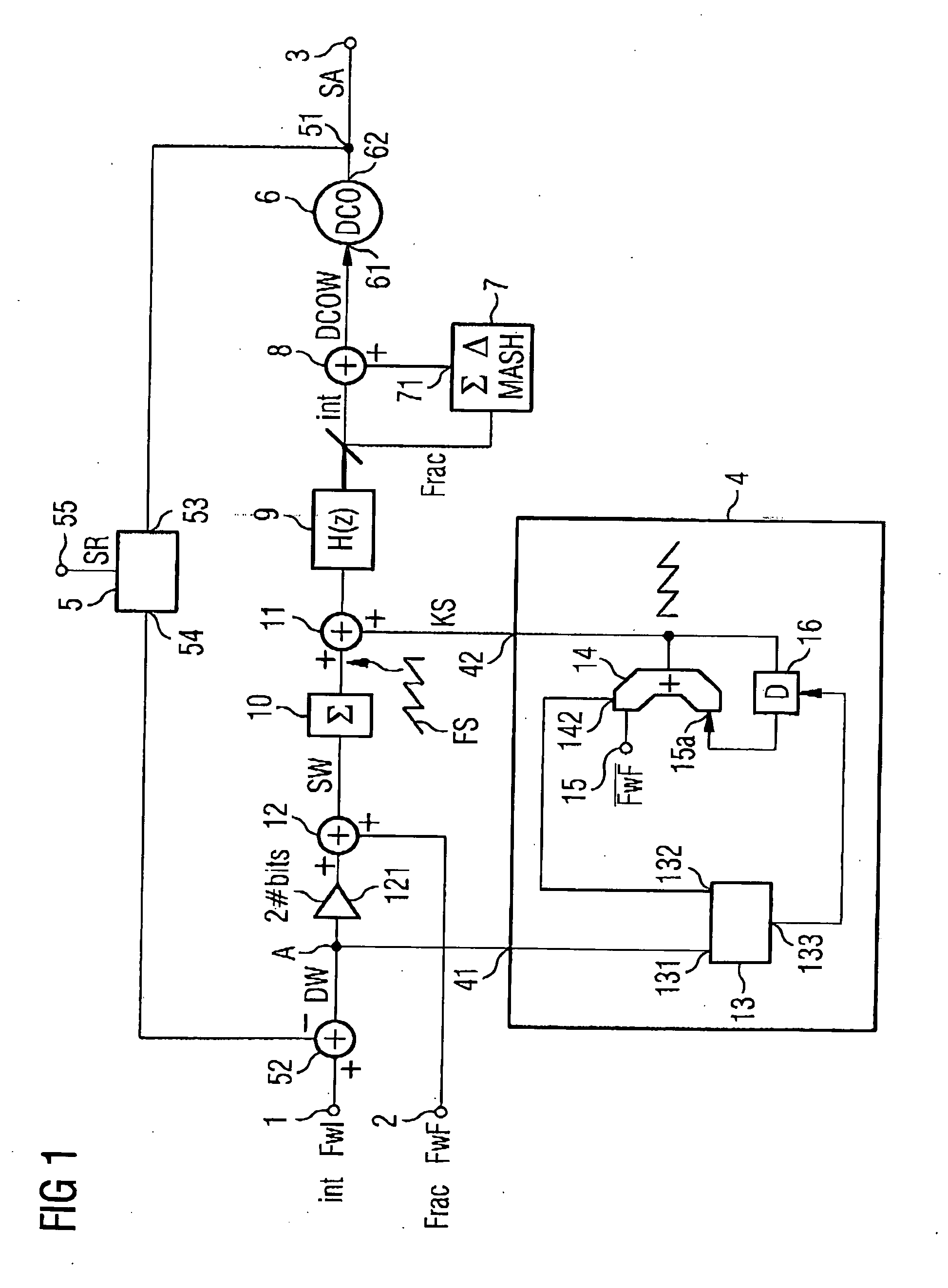
[0034]FIG. 1 shows a configurational form of a digital phase locked loop and a correction circuit. The term digital or digitally controllable phase locked loop in the following exemplary embodiment designates a control loop whose actuating signal for setting the output frequency is generated entirely by digital signal processing. The phase locked loop contains, in particular, an oscillator for providing an output signal, which oscillator uses a digital actuating signal rather than an analog actuating signal for setting its frequency. The digital actuating signal is in turn generated by digital signal processing in the forward path of the phase locked loop.

[0035] The digital phase locked loop in accordance with FIG. 1 comprises two input terminals 1 and 2 and also an output tap 3 for outputting an output signal SA. The two input terminals 1 and 2 serve for feeding in a respective frequency word, which determine the output frequency of the phase locked loop. The first frequency word,...


PUM


Abstract

A correction circuit in a digital phase locked loop is disclosed having a first terminal, a second terminal, a value-discretely tunable oscillator, an integrator, a loop filter, and a feedback path. A correction circuit is connected to an input of the integrator on the input side and to an output of the integrator on the output side. The correction circuit generates a correction word derived from an actuating word fed to the input of the integrator and a word derived from the second frequency word. A periodic error component in the frequency setting word output by the integrator can thus be corrected by the correction circuit.

Description

REFERENCE TO RELATED APPLICATIONS [0001] This application claims the benefit of the priority date of German application DE 10 2005 023 909.9, filed on May 24, 2005, the contents of which are herein incorporated by reference in their entirety. FIELD OF INVENTION [0002] The invention relates to a digital phase locked loop, and furthermore relates to a method for correcting interference components in an output signal of a digital phase locked loop. BACKGROUND OF INVENTION [0003] In telecommunications and mobile radio technology, a requirement exists that the circuits necessary for data transmission are to be realized as integrated circuits in semiconductor bodies. In this case, the development of radiofrequency assemblies is striving for an ever higher integration density and easier portability to more finely patterned semiconductor processes. The desire for easy portability is often impeded by the technology used heretofore, which is essentially based on analog signal processing. For ...

Claims


Application Information

Patent Timeline
Patent Type & Authority Applications(United States)
IPC IPC(8): H03L7/00
CPCH03L7/093H03L2207/50H03L7/181
Inventor CAMUFFO, ANDREA
Owner INTEL CORP
Why Eureka
Try Eureka