Ultrasonic flow meter including turbulators

a flow meter and ultrasonic technology, applied in the field can solve the problems of aerodynamically caused interference signals, inability to fit the surface of ultrasonic transducers, and inability to fit ultrasonic transducers, so as to facilitate the practical insertability and replacement of ultrasonic flow meter, and reduce aerodynamic interference signals

Inactive Publication Date: 2008-06-03
ROBERT BOSCH GMBH
View PDF14 Cites 11 Cited by
  • Summary
  • Abstract
  • Description
  • Claims
  • Application Information

AI Technical Summary

Benefits of technology

[0013]The use of turbulators according to the present invention in the vicinity of the ultrasonic transducers causes the formation of eddies which reduce or stabilize burble zones in the design-related pipe protrusions near the ultrasonic transducers. By locally generating turbulences, the flow adjusts better overall to the contours of the ultrasonic flow meter, thus reducing aerodynamically caused interference signals. The flow meter signal thus becomes considerably more accurate. This effect may be additionally reinforced by suitably shaping the protrusions, in particular by forming rounded edges on the protrusions.
[0014]The present invention may be applied to both linear systems such as described, for example, in British Published Patent Application No. 2 101 318 and reflection systems such as presented in European Published Patent Application No. 0 477 418. Complete or partial integration of the system into an insertion sensor which is insertable into a flow pipe is possible and facilitates practical insertability and replaceability of the ultrasonic flow meter. In particular, an electronic control device may also be integrated into the insertion sensor for activating and / or reading at least one ultrasonic transducer. The electronic control unit for reading out at least one ultrasonic transducer may, for example, contain electronics for preprocessing received signals. Appropriate electronic plug-and-socket connections may also be integrated for contacting the insertion sensor. Furthermore, at least one reflection element having a reflection surface may be integrated into the insertion sensor, making it possible to implement, for example, one of the reflection systems described above. Advantageously, the at least one reflection element is inserted into the flow pipe in such a way that fluid is able to flow on both sides of the reflection surface along the reflection body. This has the advantage in particular that if the reflection element is not in contact with the wall of the flow pipe, water droplets that may be contained in the flow are precipitated on the flow pipe as a wall film before flowing through the insertion sensor, the wall film then being able to flow through the flow pipe without wetting or contaminating the reflection surface and thus interfering with the reflection.

Problems solved by technology

The systems described in the related art, however, all have the problem that angle α in FIG. 1 must be sufficiently small for a successful flow measurement, but at least substantially smaller than 90°.
This results in the problem that it is not possible to fit the surfaces of ultrasonic transducers 116, 118 flush to the inside surface of flow pipe 110.
These turbulences cause pressure fluctuations and may result in interfering signal contributions which are superimposed on the actual ultrasonic signals as noise.
Another disadvantage of these turbulences and flow separations is that contaminants or particles such as dust, oil, or water droplets contained in the flowing medium tend to be deposited in the turbulence zones.
The disadvantage here, however, is that the layer thickness of the wedge-shaped adapter elements varies over the cross section of an emitted ultrasound beam.
This makes resonance adjustment for efficient ultrasound injection into the flowing medium difficult.

Method used


Image

  • Ultrasonic flow meter including turbulators
  • Ultrasonic flow meter including turbulators
  • Ultrasonic flow meter including turbulators

Examples


Embodiment Construction

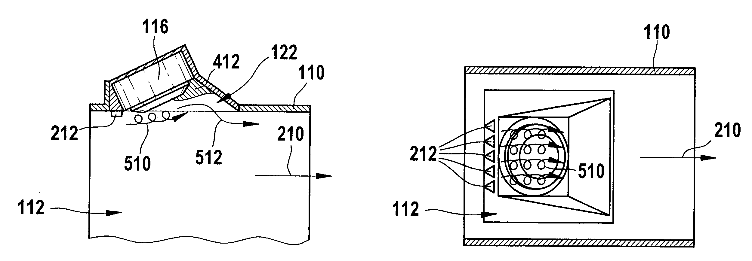
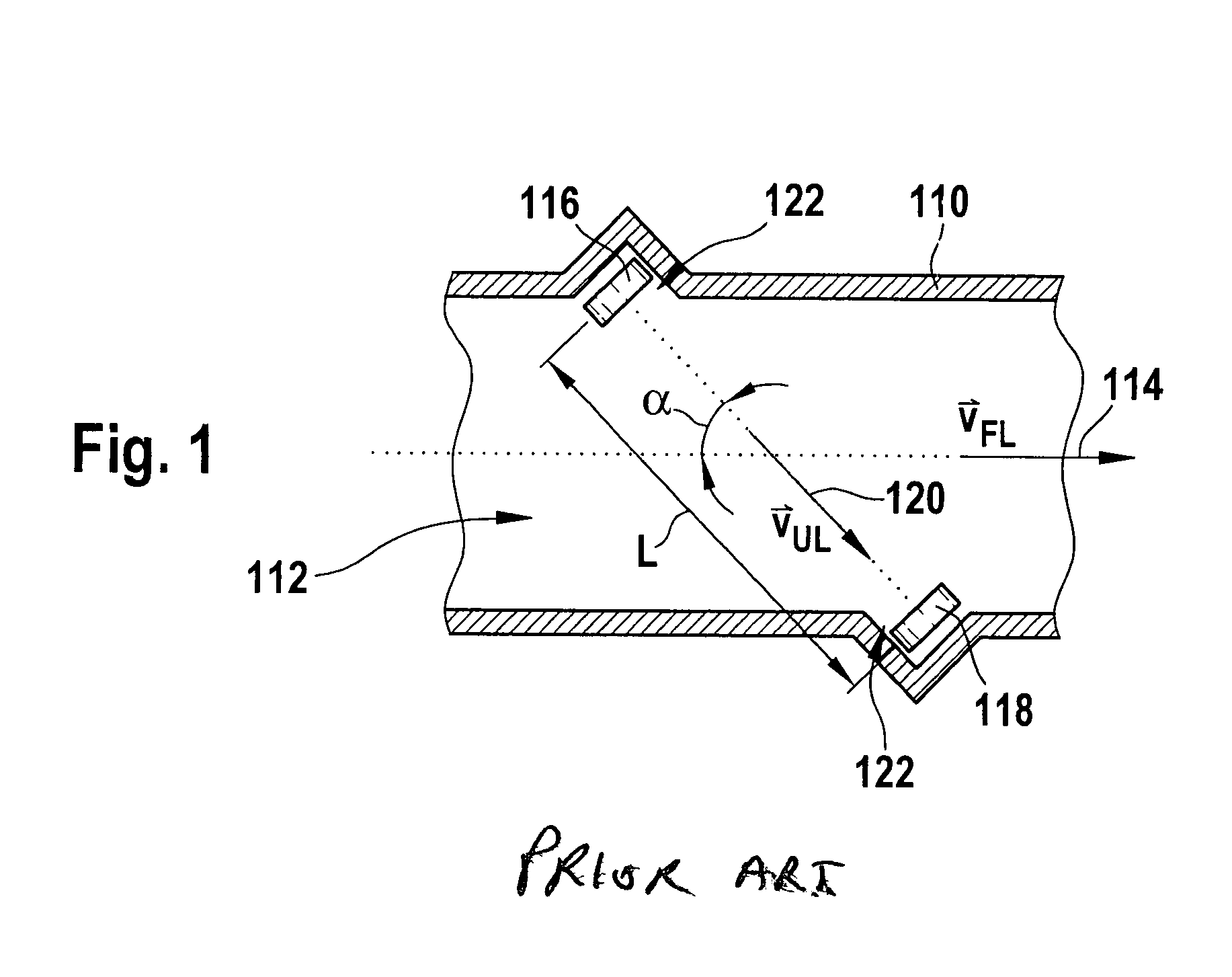
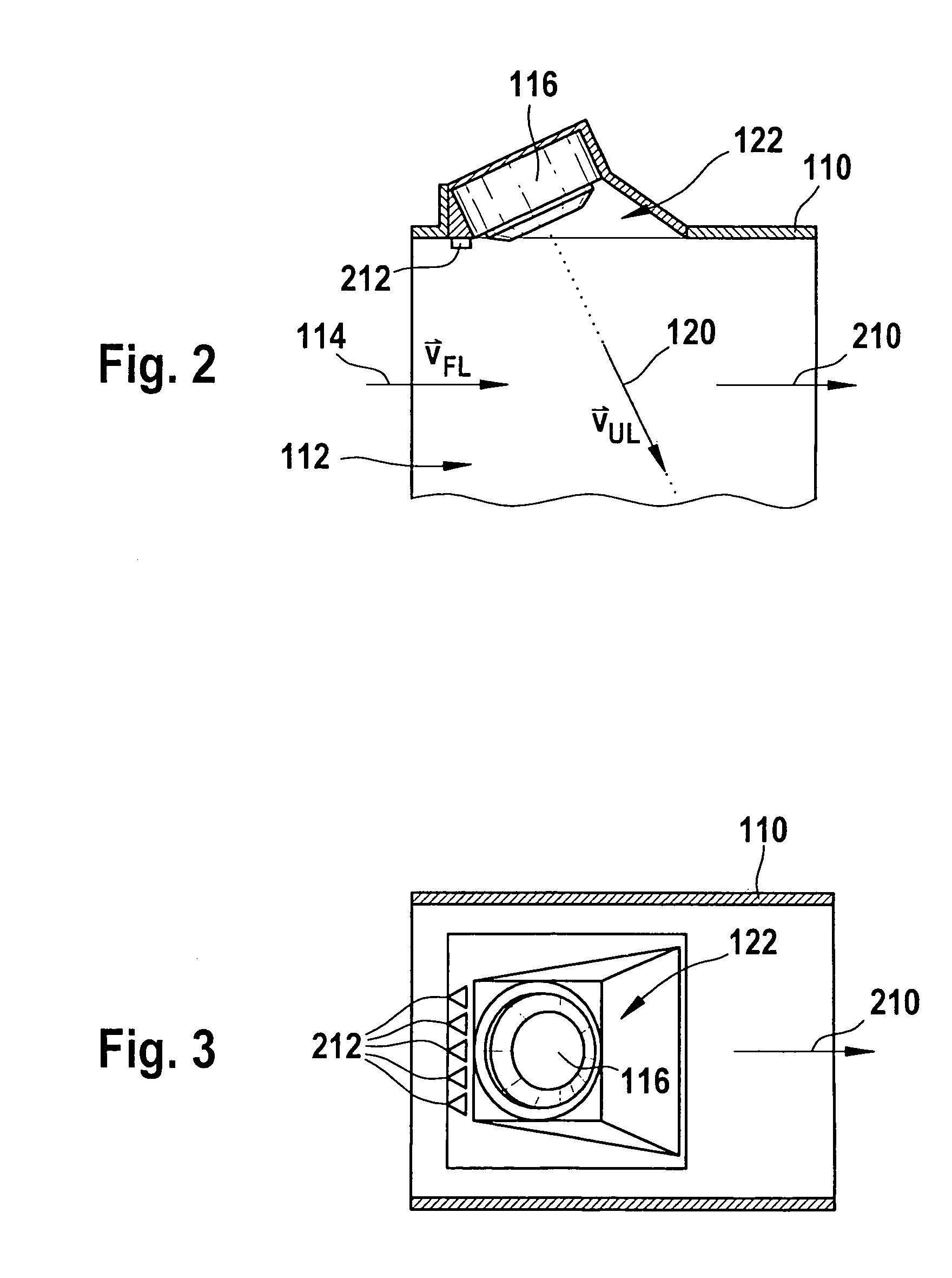
[0027]The principle of ultrasonic flow measuring has been explained above with reference to FIG. 1. Linear systems (as in FIG. 1) or reflection systems may be used, for example. FIGS. 2 through 3 show a detail of an embodiment according to the present invention of an ultrasonic flow meter. The detail includes only an area around an ultrasound sensor 116, which is embedded into a wall of a flow pipe 110. A fluid 112 having a main flow direction 210, which is parallel to flow velocity 114, flows through flow pipe 110. As explained previously with reference to FIG. 1, a protrusion 122 is formed upstream from ultrasound sensor 116, within which burble zones of the flow of fluid 112 are formed.

[0028]As the cutaway view having the section plane parallel to main flow direction 210 in FIG. 2 and the view from below according to FIG. 3 show, in this embodiment of the present invention, turbulators 212 are situated upstream from protrusion 122 on the wall of flow pipe 110. In this case, turbu...


PUM


Abstract

Measuring volume flows or mass flows in the intake system of motor vehicle internal combustion engines plays an important role in reducing harmful emissions. Therefore, an ultrasonic flow meter for measuring a flow velocity of a fluid flowing in an essentially laminar flow in the main flow direction is described. The ultrasonic flow meter has at least two ultrasonic transducers, the ultrasonic transducers being able to emit and / or receive ultrasonic waves at an angle α to the main flow direction which is different from 90°. Furthermore, the ultrasonic flow meter has at least one turbulator situated upstream from at least one ultrasonic transducer in the main flow direction of the fluid, which generates longitudinal eddies in at least one zone adjacent to the at least one ultrasonic transducer, in particular in a protrusion in a wall of a flow pipe and thus improves the flow of the fluid in this zone in the flow pipe. Wedge-shaped turbulators protruding into the flow of the fluid or flow grooves are provided in particular as turbulators. The ultrasonic flow meter is distinguished, in comparison with devices known from the related art, by improved signal-to-noise ratio and thus by higher measurement accuracy.

Description

FIELD OF THE INVENTION[0001]Ultrasonic flow meters are used in the automotive industry, in particular in the intake system of internal combustion engines, for measuring volume flow or mass flow.BACKGROUND INFORMATION[0002]Typically ultrasonic transducers are used which are capable of both emitting ultrasonic waves into a fluid and receiving ultrasonic waves. The propagation time of ultrasonic signals which are transmitted from an emitter to a receiver is influenced by the flow of the fluid. It is possible to infer the flow velocity of the fluid from the degree of influence of the propagation time.[0003]British Published Patent Application No. 2 101 318 describes an ultrasonic flow meter in which two ultrasonic transducers are mounted on opposite sides of a pipe through which a fluid flows. The transducers are situated slightly offset with respect to one another, so that ultrasonic waves emitted by one transducer and received by the second transducer propagate at an angle to the flow...

Claims


Application Information

Patent Timeline
Patent Type & Authority Patents(United States)
IPC IPC(8): G01F1/66
CPCG01F1/662G01F15/00
Inventor KONZELMANN, UWELANG, TOBIASGMELIN, CHRISTOPH
Owner ROBERT BOSCH GMBH
Why Eureka
Try Eureka