

Interference signal processing method and device
A technology that interferes with signals and equipment, applied in the field of communication, can solve problems such as high feedback overhead, difficult performance guarantee, and influence of useful signal strength
- Summary
- Abstract
- Description
- Claims
- Application Information
AI Technical Summary
Problems solved by technology
Method used
Image

Examples
Embodiment 1
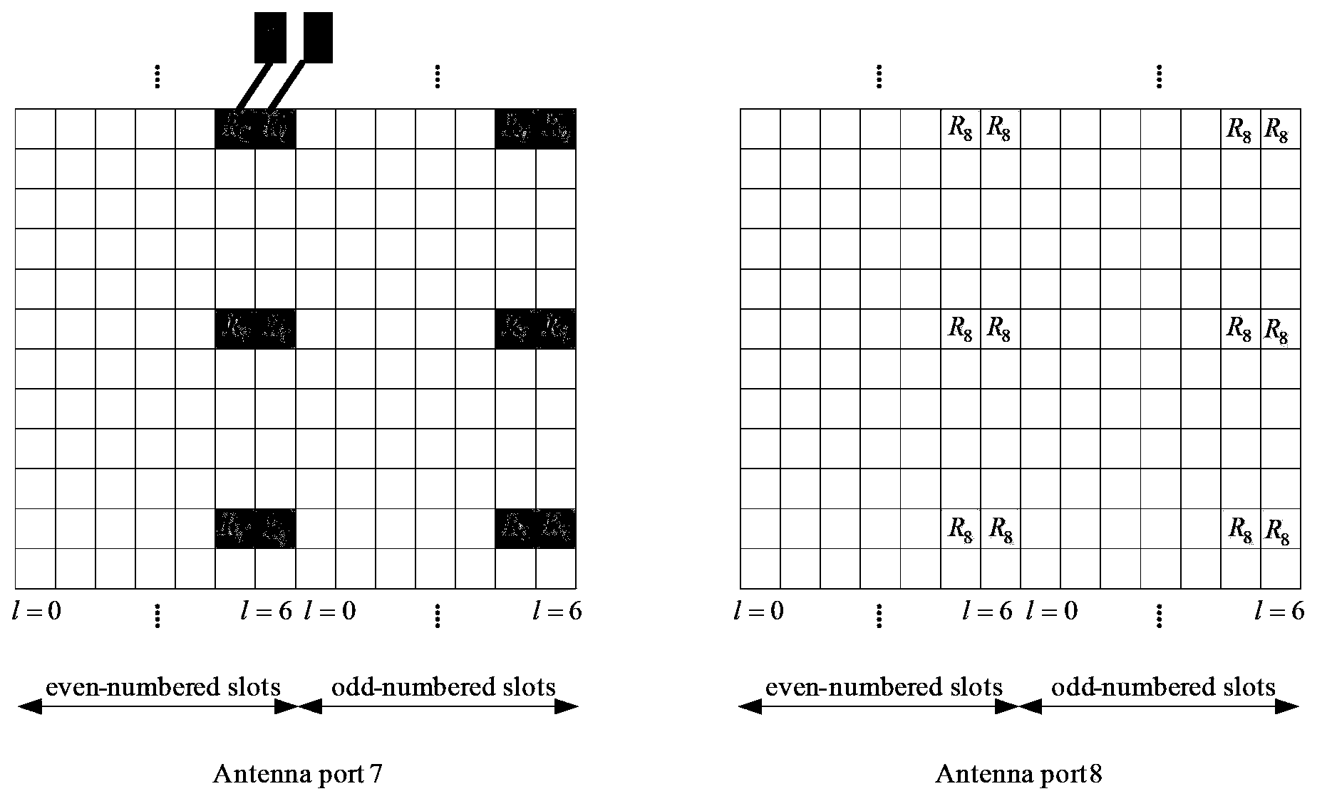
[0080]Long Term Evolution-Release9 (LTE-Rel9) introduces Multi-User Beamforming (MUBF) and uses Demodulation Reference Signal (DMRS) Antenna Port to ensure MUBF pilot Orthogonality among them to realize transparent MUBF (transparency means that UE does not need to know whether it is transmitting for MUBF, and does not need to know whether other users share the same time-frequency resources with it), and the MUBF receiver can have multiple situations, For example, the terminal performs minimum mean square error (Minimum Mean Square Error, MMSE) detection according to its own flow number, or uses Interference Reject Combining (Interference Reject Combining, IRC) detection (estimating the statistical interference covariance matrix of paired users and other interference signals, and performing IRC detection); or perform MMSE detection according to the total number of paired flows, and discard the virtual flow detection results to achieve the effect of interference suppression. The ...
Embodiment 2
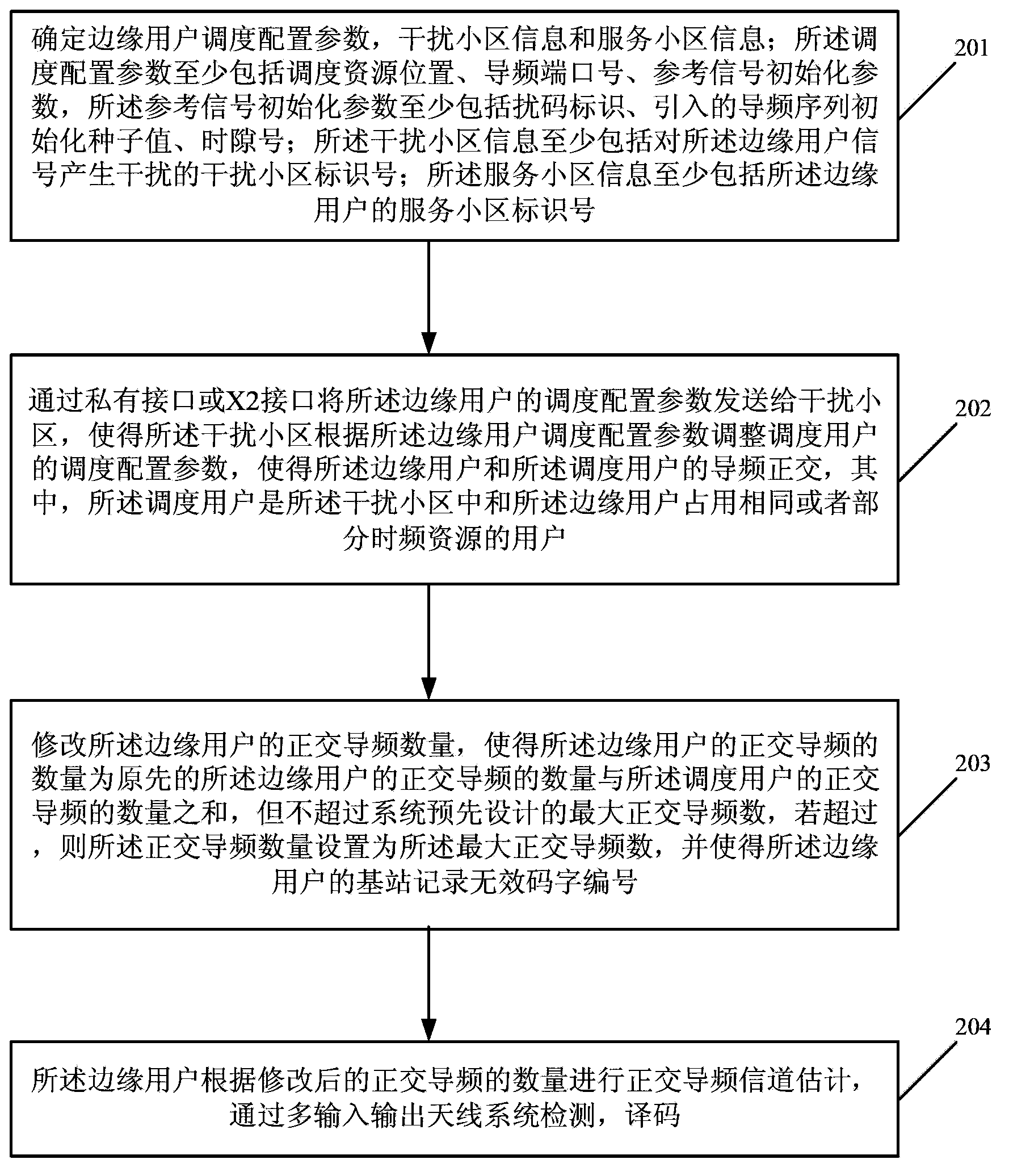
[0103] refer to figure 2 , figure 2 It is a flowchart of a method for processing an interference signal provided in Embodiment 2 of the present invention. Such as figure 2 As shown, the method includes the following steps:
[0104] Step 201, determine edge user scheduling configuration parameters, interfering cell information and / or serving cell information; the scheduling configuration parameters include at least scheduling resource location, pilot port number, and reference signal initialization parameters, and the reference signal initialization parameters include at least interference code identification, the introduced pilot sequence initialization seed value, slot number n s ; The interfering cell information includes at least the identification number of the interfering cell that interferes with the edge user signal; the serving cell information includes at least the serving cell identification number of the edge user;
[0105] Wherein, the edge user is a user wh...
Embodiment 3
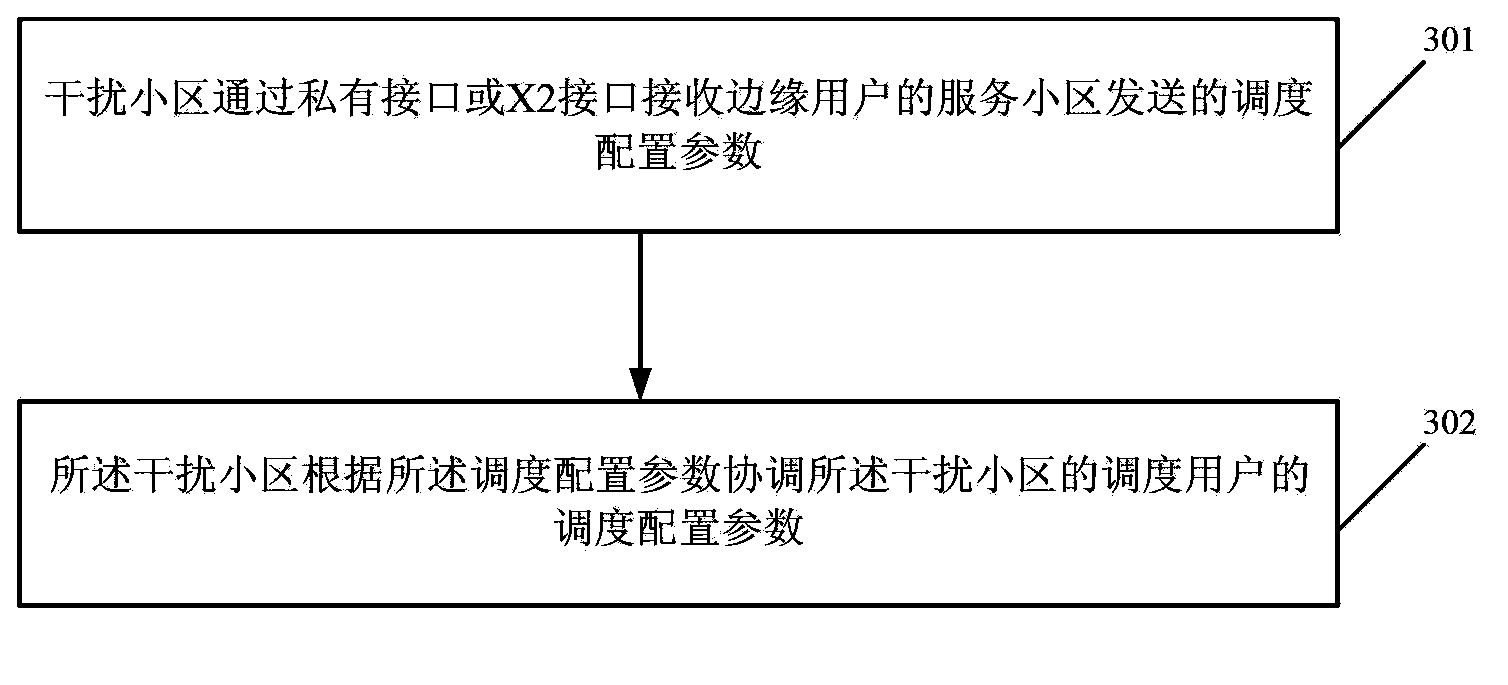
[0120] refer to image 3 , image 3 It is a flowchart of a method for processing an interference signal provided in Embodiment 3 of the present invention. Such as image 3 As shown, the method includes the following steps:
[0121] Step 301, the interfering cell receives the scheduling configuration parameters sent by the serving cell of the edge user through a private interface or an X2 interface;
[0122] Step 302, the interfering cell coordinates the scheduling configuration parameters of the scheduling users of the interfering cell according to the scheduling configuration parameters.
[0123] As an optional embodiment, the method also includes:
[0124] After receiving the coordination information, the interfering cell maintains a timer, and when no coordination request from the serving cell is received within a predetermined time, the interfering cell does not coordinate with the serving cell.
[0125] Optionally, the interfering cell coordinates scheduling configur...
PUM
 Abstract
Description
Claims
Application Information