
Electrical junction box

a junction box and electric wire technology, applied in the direction of electric/fluid circuit, electrical apparatus, vehicle components, etc., can solve the problems of electric wire coming off, electric wire entanglement with electrical components, wire repeatedly coming into contact with electrical components,

Active Publication Date: 2021-01-26
SUMITOMO WIRING SYST LTD
View PDF14 Cites 2 Cited by
  • Summary
  • Abstract
  • Description
  • Claims
  • Application Information

AI Technical Summary

Benefits of technology

The invention prevents electrical wires from interfering with other electrical components on a circuit board. This improves the overall performance of the circuit board.

Problems solved by technology

Incidentally, in a conventional structure as in Patent Document 1, an electric wire extending from a lower face of an upper electrical component block may interfere with electrical components such as relays or fuses attached to an upper face of a lower electrical component block between electrical component blocks attached in upper and lower stages, resulting in problems in which the electric wire is entangled with the electrical components, or the electric wire repeatedly comes into contact with the electrical components due to vibrations of an automobile and the coating of the electric wire comes off, for example.

Method used


Image

  • Electrical junction box
  • Electrical junction box
  • Electrical junction box

Examples


Embodiment Construction

[0015]First, embodiments of the present invention will be listed and described.

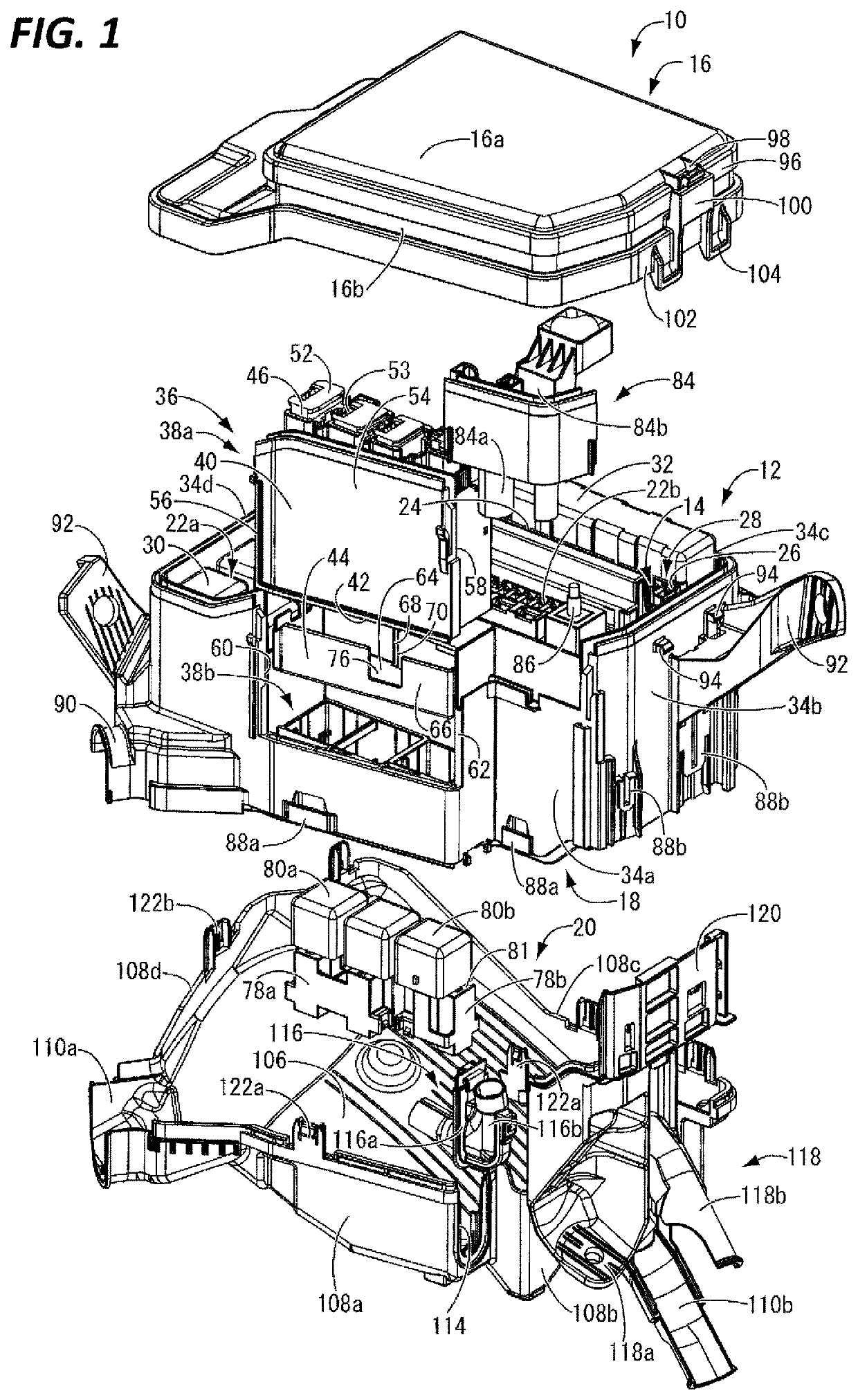
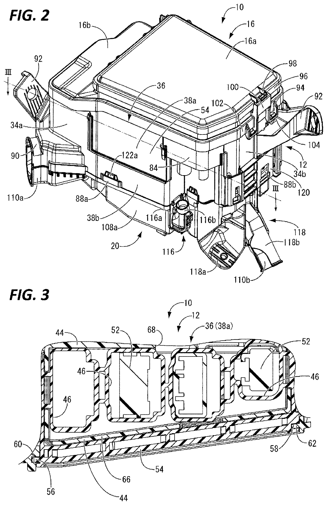
[0016]A first aspect of the present invention is directed to an electrical junction box including: a box body; an electrical component block attachment portion that is open to an upper side of the box body and extends in an upper-lower direction of the box body; and a plurality of electrical component blocks attached in multiple stages in the upper-lower direction to the electrical component block attachment portion, wherein a partitioning portion is arranged between a lower face of the electrical component block arranged on an upper side in the upper-lower direction and an upper face of the electrical component block arranged on a lower side, with a gap being interposed between the partitioning portion and each of the faces, and an electric wire extending from the lower face of the upper electrical component block is held on the partitioning portion.

[0017]According to this aspect, in an electrical juncti...


PUM


Abstract

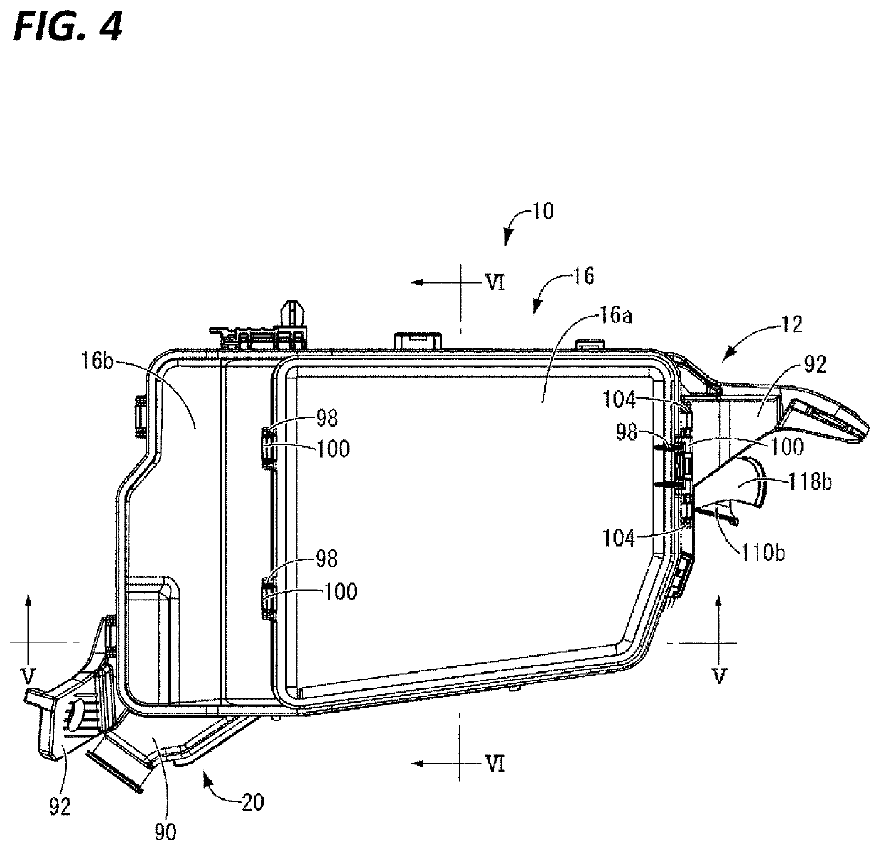
Provided is an electrical junction box 10 including: a box body 12; an electrical component block attachment portion 36 that is open to an upper side of the box body 12 and extends in an upper-lower direction of the box body 12; and a plurality of electrical component blocks 38a and 38b attached in multiple stages in the upper-lower direction to the electrical component block attachment portion 36. A partitioning portion 44 is arranged between a lower face 42 of the electrical component block 38a arranged on an upper side in the upper-lower direction and an upper face 81 of the electrical component block 38b arranged on the lower side thereof, with gaps 82a and 82b being interposed between the partitioning portion and the faces. An electric wire 50 extending from the lower face 42 of the upper electrical component block 38a is held on the partitioning portion 44.

Description

CROSS REFERENCE TO RELATED APPLICATIONS[0001]This application is a national phase of PCT application No. PCT / JP2019 / 000369, filed on 9 Jan. 2019, which claims priority from Japanese patent application No. 2018-002137, filed on 10 Jan. 2018, all of which are incorporated herein by reference.TECHNICAL FIELD[0002]The present invention relates to an electrical junction box that is mounted in an engine room of an automobile and the like.BACKGROUND[0003]Conventionally, box bodies of electrical junction boxes mounted in engine rooms of automobiles and the like accommodate various electrical components such as relays and fuses and efficiently distribute power sources, for example. In particular, following recent demand for a larger number of electrical devices and smaller vehicles, an electrical junction box including a box body to which electrical component blocks such as relay blocks are attached in upper and lower stages is proposed as described in Japanese Patent No. 5800628 (Patent Doc...

Claims


Application Information

Patent Timeline
Patent Type & Authority Patents(United States)
IPC IPC(8): B60R16/023H02G3/08H02G3/18
CPCH02G3/081B60R16/0239H02G3/18B60R16/0238
Inventor MIYAMOTO, YUJI
Owner SUMITOMO WIRING SYST LTD
Learn More