Mainsail reefing system

a reefing system and mainsail technology, applied in the field of marine equipment, can solve the problems of requiring at least one crewmember, affecting the safety of the crew, and the reefing winch can also present problems for the crew, so as to minimize the amount of line and minimize the load of the sail

Active Publication Date: 2009-04-02
MCKIM MICHAEL
View PDF18 Cites 3 Cited by
  • Summary
  • Abstract
  • Description
  • Claims
  • Application Information

AI Technical Summary

Benefits of technology

[0019]The invention is a system and method for reefing sails. In its simplest form the invention enables a single control line to pull two reefing lines down to the mainsail boom, thereby minimizing the amount of line and also the number of lines that must be hauled into the cockpit to deploy the reef. The total mechanical load generated by the reef is split between the two separate reefing lines on the mainsail and then brought together again at a drum assembly, thereby spreading out and minimizing the loads on the sail while still allowing the system to be operated by a single control line led from the drum assembly to the cockpit.
[0021]The preferred embodiment of the levelwind mechanism is comprised entirely of extrudable rod and tube profiles that fasten together with machine screws. This design reduces material wastage and machining costs to a minimum, while at the same time eliminating the need for welds that can lead to heat-related distortion of close-fitting components.
[0023]A variety of housings can be fitted over the reefing mechanism to prevent loose line or sail material from interfering with moving components.
[0024]The reefing system may also include an outhaul fairlead car configured to hold the leech-end reefing line in proper alignment with the sheave on a boom-mounted fairlead block and to prevent loose sail material from hindering the movement of the leech-end reefing line
[0026]In preferred embodiments the drum assembly is constructed by securing all drum components to a single tube. This design for the drum assembly allows for lower manufacturing costs than are typically incurred for fabricating a drum assembly from separate drums. The tube may be made of extruded aluminum. This preferred embodiment of the drum assembly includes: a tube; a center drum disc coaxially attached to the tube; two end discs fixed to the ends of the tube; and a threaded disc coaxially attached to the tube, the threaded disc having a larger diameter than the tube; wherein the section of tube between a first end disc and the threaded disc is a first drum for collecting a first reefing line, the section of tube between the second end disc and the center disc is a second drum for collecting a second reefing line, and the section of tube between the threaded disc and the center disc is a third drum, and wherein the threaded disc and the third drum are configured to enable a cockpit line to be fixed to the threaded disc and wound around the threaded disc and the third drum. The threaded disc may be attached to the tube by mechanical fasteners and keyways. Furthermore, leverage battens may be attached to the third drum to increase the diameter of the third drum, thus increasing the leverage available to the crew during the reefing process.

Problems solved by technology

Perhaps the biggest drawback to slab reefing is that it requires at least one crewmember to leave the cockpit and go to the mast.
This can be a potentially hazardous maneuver, especially if it is undertaken at night and / or in rough and slippery conditions, as is usually the case when the wind has increased to a point where a deep mainsail reef is warranted.
With a slab reefing system, the location of the reefing winch can also present problems for the crew.
This position can be awkward and dangerous, since the leeward side of a sailing vessel is typically heeled to a steep angle and is often awash with wave action during windy conditions.
Furthermore, slab reefing requires the crew to haul in a long length of reefing line to complete the reef.
Moreover, both dual and single line reefing systems require the crew to pull in long lengths of line.
These potential loads are high enough so that a Hoyt single line reefing system is generally limited to use on sailing vessels under thirty-two feet in length.
The elimination of battens constitutes a significant performance loss, since without battens the sail cannot hold an ideal aerodynamic shape in a variety of wind conditions.
Moreover, both in-mast and in-boom reefing systems—where the mainsail is rolled around a full-length rod inside the boom instead of inside the mast—require the elimination of mainsail roach, which significantly reduces the total available surface area of the mainsail and consequently reduces overall sail performance.
In-mast and in-boom mainsail reefing systems are expensive and complicated to install.
Furthermore, if an in-mast furling system should jam for any reason, the mainsail could become stuck in the raised position.
In a gale at sea, this situation could be analogous to a stuck accelerator in a car, with no easy solutions at hand.

Method used


Image

  • Mainsail reefing system
  • Mainsail reefing system
  • Mainsail reefing system

Examples


Embodiment Construction

[0070]The present invention will now be described in detail with reference to the drawings, which are provided as illustrative examples of the invention so as to enable those skilled in the art to practice the invention. Notably, the figures and examples below are not meant to limit the scope of the present invention to a single embodiment, but other embodiments are possible by way of interchange of some or all of the described or illustrated elements.

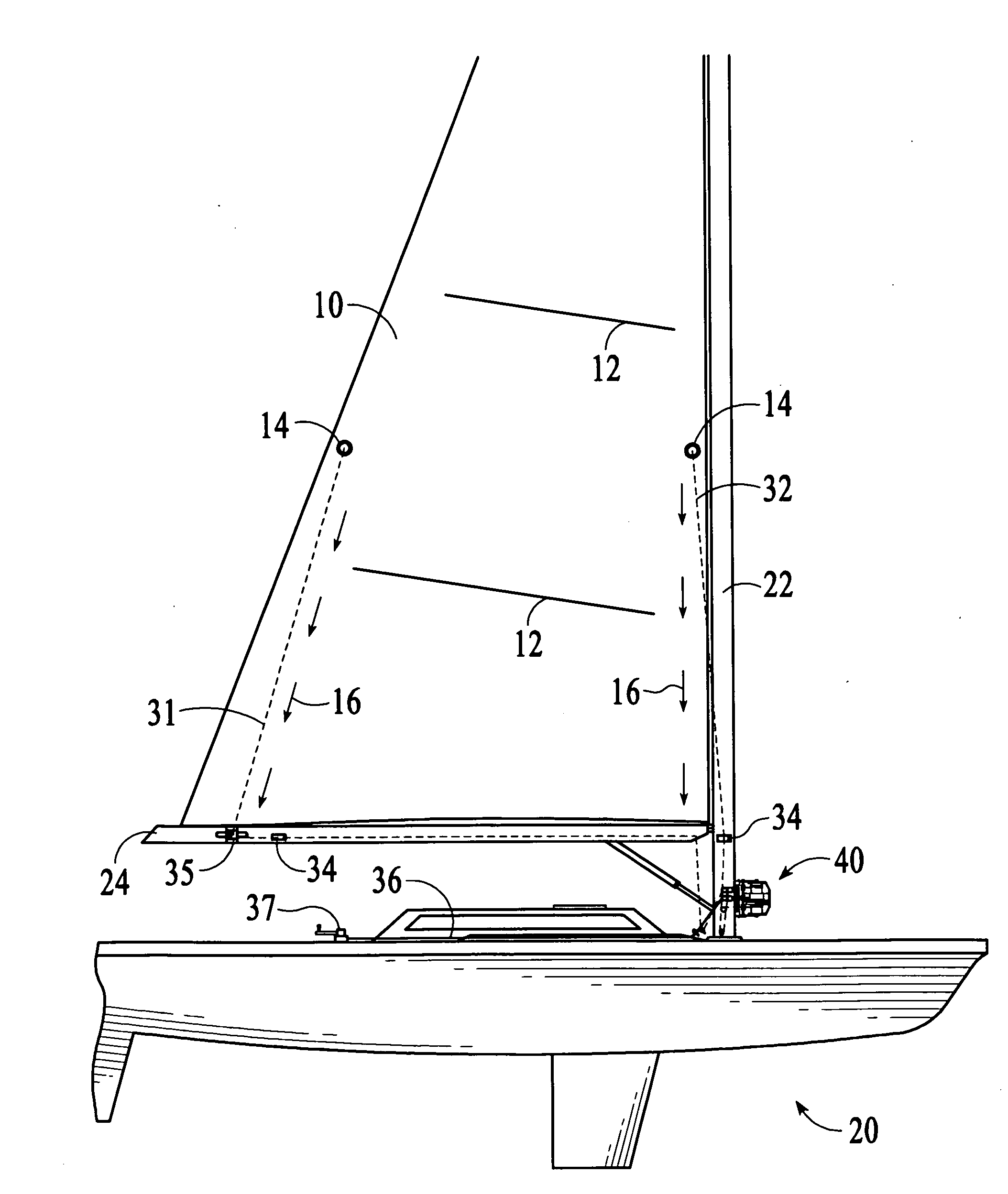
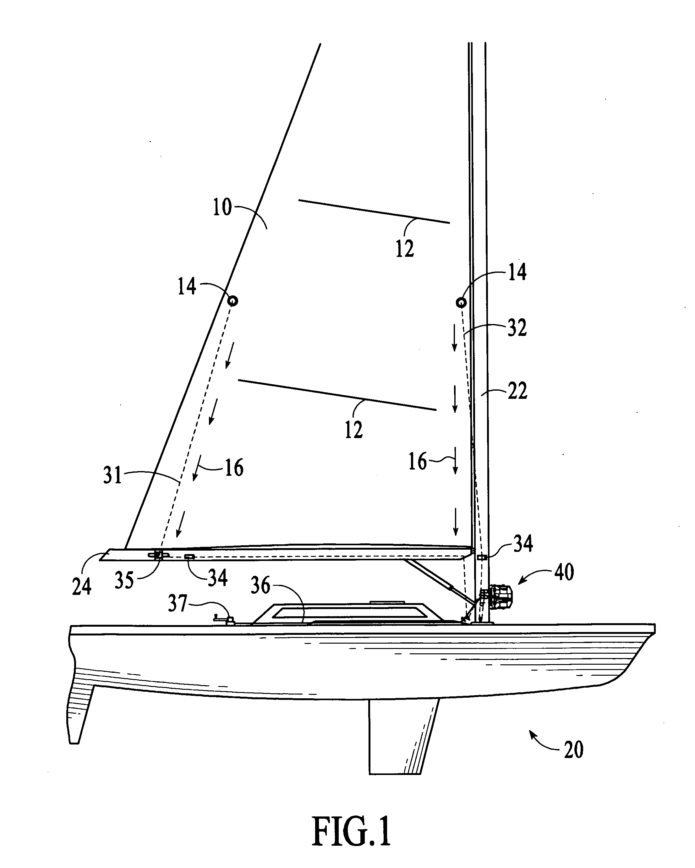
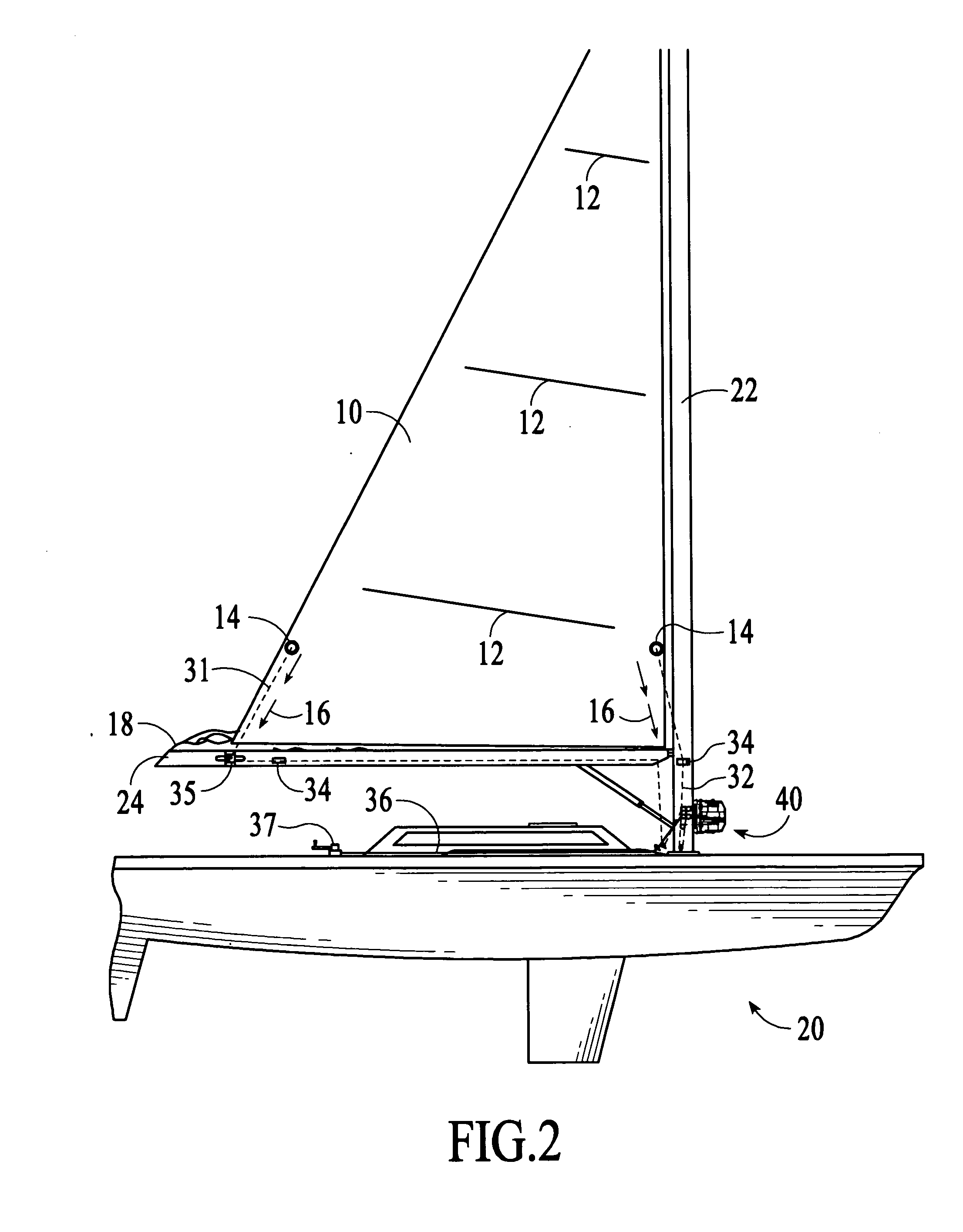
[0071]The mainsail reefing system of the invention is a mechanical system designed to allow sailboats of any size to reef the mainsail by pulling on a single line led to the vessel's cockpit. To “reef” a mainsail means to reduce the working surface area of the sail, so that the vessel does not heel excessively as wind strength increases. The mainsail reefing system of the invention maximizes mainsail reefing efficiency by greatly reducing the total amount of line the crew must haul in to complete the reef, relative to conventional main...


PUM


Abstract

A mainsail reefing system comprises: a drum assembly including first and second coaxial drums for collecting luff-end and leech-end reefing lines, respectively; a drive mechanism for rotating the drum assembly; and a levelwind mechanism including a cam shaft configured to convert rotational motion to reciprocating motion, and first and second line guides mechanically coupled to the cam shaft, where the line guides are configured to move in a reciprocating motion across the width of the first and second drums, respectively, for guiding the reefing lines onto their respective drums. The levelwind mechanism is mechanically coupled to the reefing mechanism for coordination of movement of the line guides with rotation of the drum assembly. A preferred drive assembly comprises a third drum attached coaxially to the first and second drums, and a larger diameter threaded disc coaxially attached to an end of the third drum. During the reefing process a cockpit line is pulled off the third drum and then transitions to the larger diameter threaded disc, providing extra leverage during the outhaul tensioning of the mainsail.

Description

CROSS-REFERENCE TO RELATED APPLICATIONS[0001]This application claims the benefit of U.S. Provisional Application Ser. No. 60 / 969,574, filed Aug. 31, 2007, which is expressly incorporated by reference herein.BACKGROUND OF THE INVENTION[0002]1. Field of the Invention[0003]This invention relates to the field of marine equipment, and more particularly to systems for reefing sails on sailboats.[0004]2. Description of the Related Art[0005]Reefing is a procedure used in sailing for reducing the area of a sail on a sailboat or sailing ship. Reefing can improve the boat's stability and reduce the risk of capsizing, broaching, or damaging sails or boat hardware in strong winds.[0006]There are three common methods of reefing: slab reefing, conventional dual line and single line reefing, and in-mast and in-boom mainsail reefing.Slab Reefing[0007]Slab reefing systems require the sailing vessel's crew to leave the cockpit and perform the mainsail reef while standing at the mast. Using this system...

Claims


Application Information

Patent Timeline
Patent Type & Authority Applications(United States)
IPC IPC(8): B63H9/08
CPCB63H9/1042B63H9/1035
Inventor MCKIM, MICHAEL
Owner MCKIM MICHAEL
Why Eureka
Try Eureka