Pressure-detecting sensor

a technology of pressure detection and sensor, applied in piezoelectric/electrostrictive/magnetostrictive devices, instruments, computing, etc., can solve the problems of difficult operation input device disclosed in patent literature 2 may not be able to surely detect pressing force, etc., to increase the precision of detection of pressing for

Active Publication Date: 2018-12-04
MURATA MFG CO LTD
View PDF26 Cites 0 Cited by
  • Summary
  • Abstract
  • Description
  • Claims
  • Application Information

AI Technical Summary

Benefits of technology

[0012]Therefore, it is an object of the present invention to provide a pressure-detecting sensor that can more surely detect a pressing force.
[0014]In this configuration, strain in the plate member that is produced when the operation surface of the plate member is depressed causes the piezoelectric film to be effectively strained and generate charge. In this case, the use of the present configuration eliminates the presence of a location of pressure where the charge is 0, thus making it possible to surely detect charge that is generated by the piezoelectric film in response to a pressing force.
[0016]This configuration can more surely prevent charge from becoming 0, thus making it possible to more surely detect a pressing force.
[0018]In this configuration, the piezoelectric sensor is attached to such a location as to easily sense strain produced when the operation surface of the plate member is pressed. This makes it possible to more surely detect a pressing force.
[0020]In this configuration, strain produced when the operation surface of the plate member is pressed causes charge to be produced by the piezoelectric strain constant d14 of polylactic acid. Polylactic acid produces charge by expanding and contracting in a planar direction, thus making it possible to increase the precision of detection of a pressing force from strain in the plate member.
[0021]This invention makes it possible to surely detect a pressing force applied to the operation surface.

Problems solved by technology

However, the configurations of the conventional technologies described above present the following problems.
This may make it impossible to surely detect a pressing force.
This makes it even harder to surely detect a pressing force.
Further, the operation input device disclosed in Patent Literature 2 may not be able to surely detect a pressing force, because the matrices of electrodes are composed of linear electrodes and the operation input device detects depression-induced charge with such matrices of electrodes.
This makes it even harder to surely detect a pressing force, as in the case of the operation input device disclosed in Patent Literature 1.

Method used


Image

  • Pressure-detecting sensor
  • Pressure-detecting sensor
  • Pressure-detecting sensor

Examples


Embodiment Construction

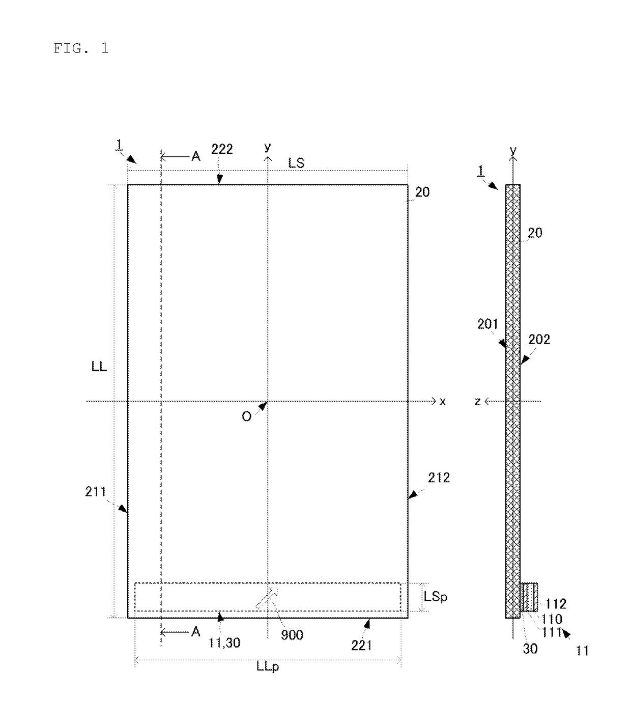
[0027]A pressure-detecting sensor according to an embodiment of the present invention is described with reference to the drawings. FIG. 1 is a plan view and a side cross-sectional view of the pressure-detecting sensor according to the embodiment of the present invention. The cross-sectional view shown in FIG. 1 is one taken along line A-A in the plan view.

[0028]The pressure-detecting sensor 1 includes a piezoelectric sensor 11, a plate member 20, and an attaching member 30. The piezoelectric sensor 11 includes a piezoelectric film 110 and detecting electrodes 111 and 112.

[0029]The piezoelectric film 110 is composed of polylactic acid (PLA), or more specifically, poly(L-lactic acid) (PLLA). The piezoelectric film 110 takes the form of an oblong flat membrane having a length (longitudinal-direction length) LLp and a width (transverse-direction length) LSp that is shorter than the length LLp. It should be noted that although the piezoelectric film 110 is thus in the shape of an oblong ...


PUM


Abstract

A pressure-detecting sensor that includes a piezoelectric sensor, a rectangular plate member, and an attaching member. The piezoelectric sensor is attached to the plate member via the attaching member so that the piezoelectric sensor is located in the vicinity of an end of the plate member in the longitudinal direction of the plate member, and such that the longitudinal direction of the piezoelectric sensor is parallel to the transverse direction of the plate member. The attaching member is composed of a sticky agent having an elastic constant of 106 Pa or lower. The piezoelectric sensor has a shape having aspect ratio of 2.5 or higher.

Description

CROSS REFERENCE TO RELATED APPLICATIONS[0001]The present application is a continuation of International application No. PCT / JP2014 / 070437, filed Aug. 4, 2014, which claims priority to Japanese Patent Application No. 2013-163148, filed Aug. 6, 2013, the entire contents of each of which are incorporated herein by reference.FIELD OF THE INVENTION[0002]The present invention relates to a pressure-detecting sensor that detects a pressing force with which an operation surface is depressed.BACKGROUND OF THE INVENTION[0003]Conventionally, various types of operation-detecting sensors that detect an operation performed on an operation surface by an operator have been devised. Examples of operation-detecting sensors include a capacitive type, a thermal resistance type, piezoelectric acoustic type, an infrared sensor type, and the like. In order to detect a pressing force applied to an operation surface, it is necessary to install a pressure-detecting sensor that is different from these types of...

Claims


Application Information

Patent Timeline
Patent Type & Authority Patents(United States)
IPC IPC(8): G06F3/041H01L41/113H01L41/193
CPCG06F3/0414H01L41/193H01L41/1132G06F3/0416H10N30/302H10N30/857
Inventor KAWAMURA, HIDEKIANDO, MASAMICHI
Owner MURATA MFG CO LTD
Why Eureka
Try Eureka