
Disk reproducing apparatus

a technology of reproducing apparatus and disc, which is applied in the direction of error detection/correction, instruments, digital computer details, etc., can solve the problems of causing trouble, data error occurring due to mixing noise into data itself, and affecting the accuracy of data, etc., and causing trouble malfunctions such as images or sound breaks are feared

Inactive Publication Date: 2007-08-14
FUNAI ELECTRIC CO LTD
View PDF17 Cites 5 Cited by
  • Summary
  • Abstract
  • Description
  • Claims
  • Application Information

AI Technical Summary

Benefits of technology

The invention is a disk reproducing apparatus that reduces communication errors between two microcomputers by detecting and addressing them quickly. This is achieved by adding a byte for error detection to data sent from one microcomputer to another, and then performing error detection on the received data using that byte. The apparatus also includes signal lines for transmitting control signals and data signals between the two microcomputers, and a mechanism for shifting between different states based on the status of the communication. The technical effect of this invention is to minimize the likelihood of communication errors and improve the reliability of the disk reproducing apparatus.

Problems solved by technology

However, in the techniques disclosed in the publications, there is a problem that a data error occurring due to mixing of noise into data itself is missed.
Because of this, even when the techniques disclosed in the publications are applied to communication between two microcomputers for control incorporated into the disk reproducing apparatus, a problem that a malfunction of causing trouble in which an image or a sound breaks occurs is feared.

Method used


Image

  • Disk reproducing apparatus
  • Disk reproducing apparatus
  • Disk reproducing apparatus

Examples


Embodiment Construction

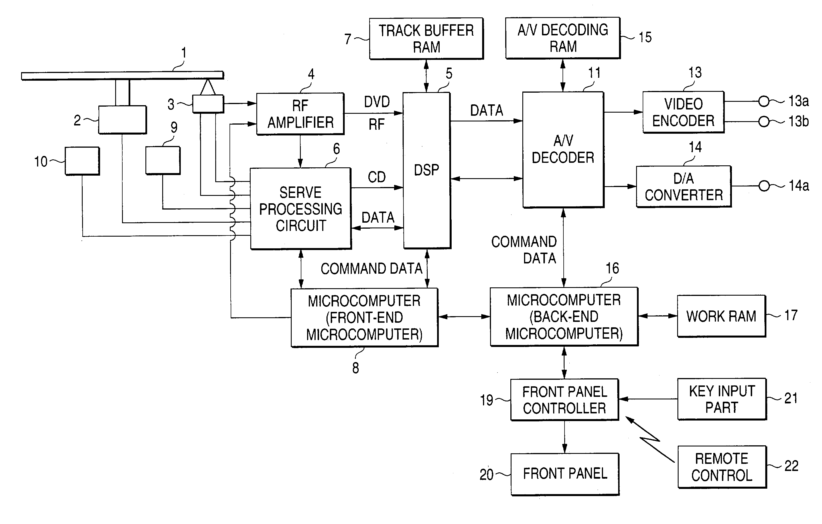
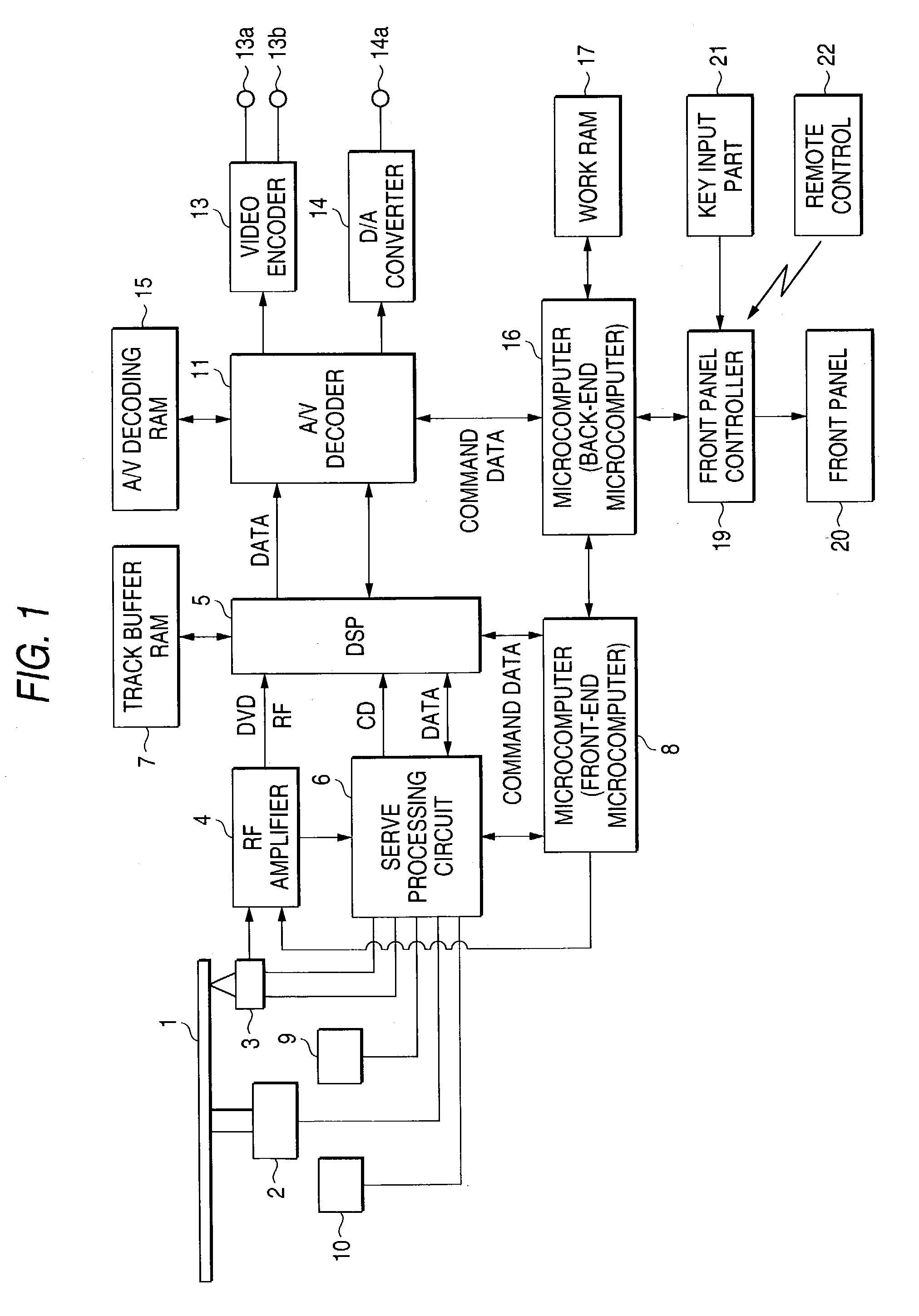
[0024]An embodiment of the invention will be described below with reference to the drawings. FIG. 1 is a block diagram of a disk reproducing apparatus which is one embodiment of the invention. An output of a pickup 3 for detecting information from a disk 1 rotated and driven by a disk motor 2 is guided to a signal processing circuit 5 and a servo processing circuit 6 through an RF amplifier 4, and an output of the servo processing circuit 6 is guided to a digital signal processor (hereinafter called “DSP”) 5.

[0025]Also, track buffer RAM (Random Access Memory) 7 for once storing data amplified by the RF amplifier 4 and decoded compliant with DVD standards (where data is compressed by MPEG (Motion Picture Expert Group) here) is connected to the DSP 5. These RF amplifier 4, DSP 5 and servo processing circuit 6 are controlled by a microcomputer 8. Thus, the microcomputer 8 performs control of an operation for reproducing information from the disk 1 and is hereinafter referred to as “a f...


PUM

PropertyMeasurementUnit
timeaaaaaaaaaa

Abstract

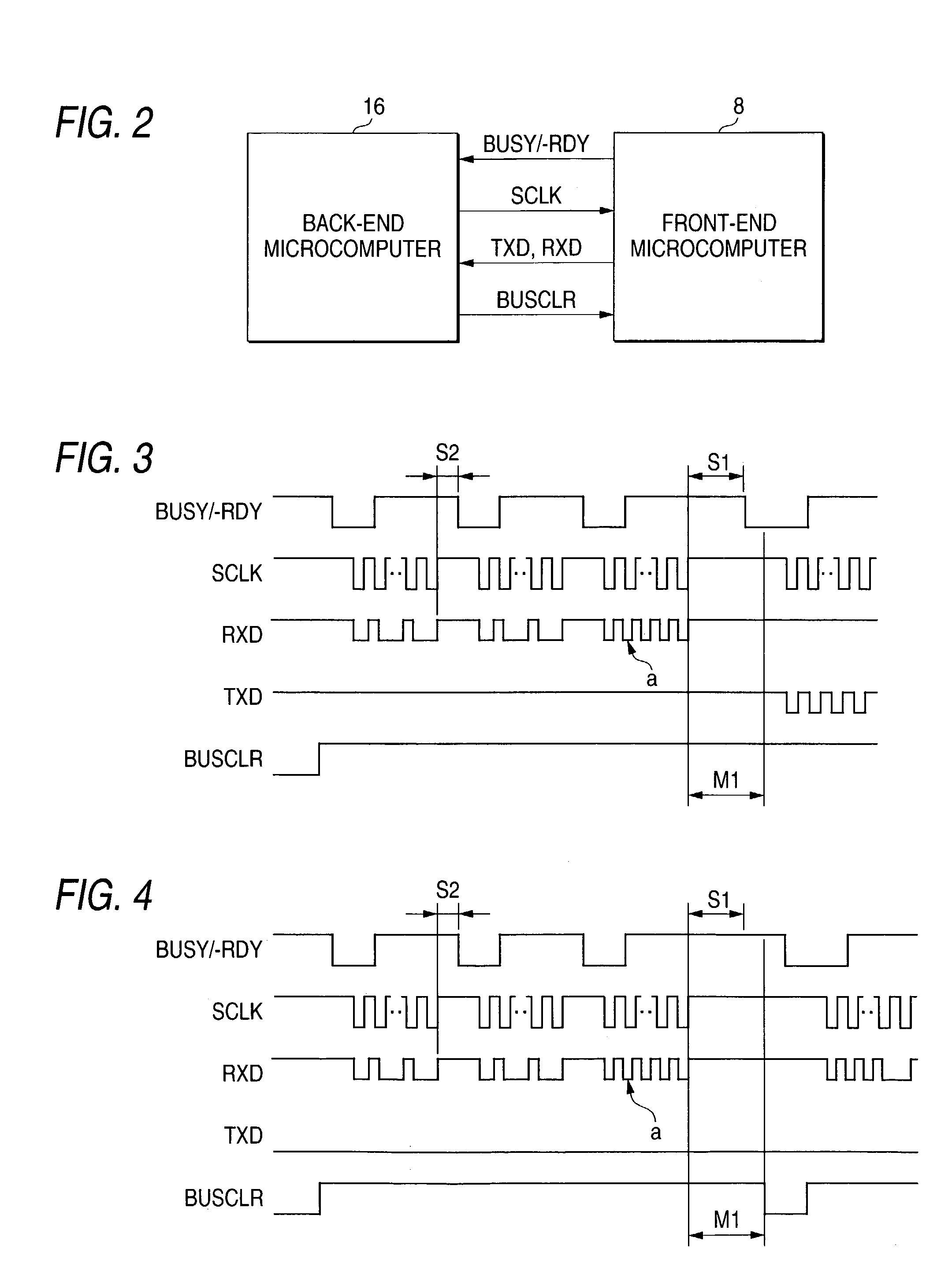
With regard to two-way clock synchronous serial communication conducted between a back-end microcomputer 16 and a front-end microcomputer 8, data is sent from the front-end microcomputer 8 to the back-end microcomputer 16 in a form of responding to data sent from the back-end microcomputer 16 between the back-end microcomputer 16 and the front-end microcomputer 8 and from the sending side, sending target data formed by adding a byte for error detection to a byte which is the original sending target is sent and in the receiving side, when a byte corresponding to the byte for error detection is received, error detection of received data is performed using said byte and when an error is detected in the received data, by providing notification to the effect that a communication error occurrs from the receiving side to the sending side.

Description

BACKGROUND OF THE INVENTION[0001]The present invention relates to a disk reproducing apparatus for reproducing information recorded on a disk-shaped record medium such as a DVD (Digital Video Disc), and to the disk reproducing apparatus for incorporating two microcomputers and controlling the entire operation by cooperation between these microcomputers.[0002]In a disk reproducing apparatus for reproducing information recorded on a DVD which is a kind of disk-shaped record medium, the entire operation may be controlled by cooperation between two microcomputers. Clock synchronous serial communication is generally conducted between these two microcomputers.[0003]Here, in the clock synchronous serial communication, by adopting techniques disclosed in publications of the Unexamined Japanese Patent Application Publication Nos. Hei6-243052 and 2000-201198, communication can be recovered even in case that a communication error resulting from mixing of noise into a clock occurs.[0004]However...

Claims


Application Information

Patent Timeline
Patent Type & Authority Patents(United States)
IPC IPC(8): G06F11/00G06F15/177G06F3/06G06F13/00G11B20/10H02H3/05H04L1/16
CPCG06F3/0614G06F3/0632G06F3/0674
Inventor FUJITA, YOSHIKAZU
Owner FUNAI ELECTRIC CO LTD
Learn More