Supercharge Your Innovation With Domain-Expert AI Agents!

Push-button switch capable of adjusting output power

a push-button switch and output power technology, applied in the field of push-button switches, can solve the problems of laborious operation of the operator to complete the operation of the open and closed circuits, inconvenient overall operation, etc., and achieve the effect of reducing the size of the push-button switches and not requiring greater effor

Active Publication Date: 2018-12-04
DEFOND COMPONENTS +1
View PDF2 Cites 0 Cited by
  • Summary
  • Abstract
  • Description
  • Claims
  • Application Information

AI Technical Summary

Benefits of technology

[0004]In view of the shortcomings of the prior art, the primary object of the present invention is to provide a push-button switch capable of adjusting output power. The structure of the push-button switch is compact. Under the same condition of having the power adjustment function, the size of the push-button switch is reduced. The interior configuration of the push-button switch takes advantage of the principle of elastic deformation and restoration, so that the operator can complete the operation of the open circuit and closed circuit, without greater effort. The present invention has a labor-saving and ergonomic design.
[0013]When the drive mechanism drives the connecting elastic plate to be pressed downward, one end of the connecting elastic plate is engaged with the first slot to be immovable, and the other end connected with the upper terminal is continuously pressed downward so that the connecting elastic plate is deformed and curved. The upper terminal is in contact with the lower terminal, and the circuit is closed. When the force from the drive mechanism to press the connecting elastic plate disappears, the connecting elastic plate is restored by means of its elasticity. The upper terminal and the lower terminal are disconnected and the circuit is disconnected. The structure is compact. Under the same condition of having the power adjustment function, the size of the push-button switch is reduced. The interior configuration of the push-button switch takes advantage of the principle of elastic deformation and restoration, so that the operator can complete the operation of the open circuit and closed circuit, without greater effort. The present invention has a labor-saving and ergonomic design.

Problems solved by technology

It is laborious for the operator to complete the operation of the open circuit and closed circuit.
The overall operation is inconvenient, without an ergonomic design.

Method used


Image

  • Push-button switch capable of adjusting output power
  • Push-button switch capable of adjusting output power

Examples


Embodiment Construction

[0016]Embodiments of the present invention will now be described, by way of example only, with reference to the accompanying drawings.

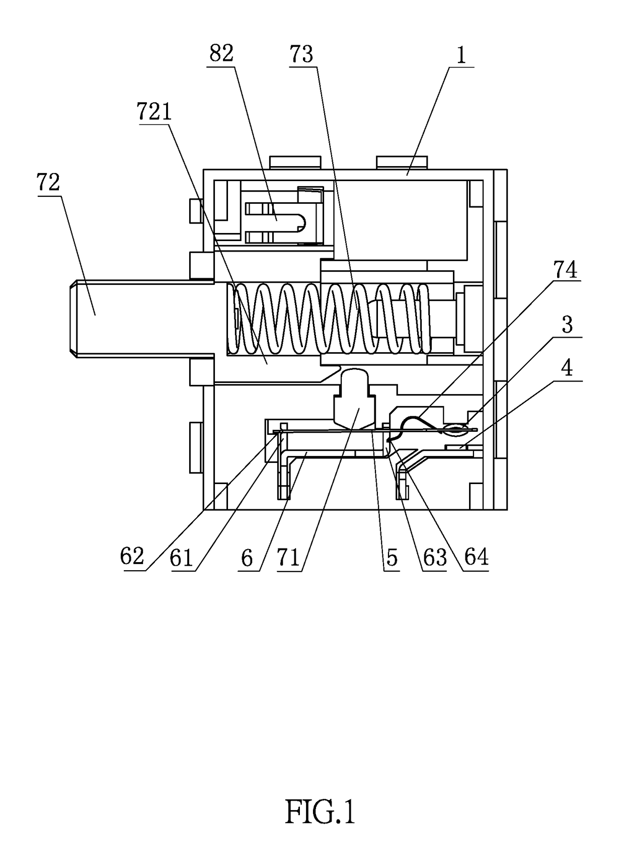
[0017]As shown in FIG. 1 and FIG. 2, a push-button switch capable of adjusting output power according to an embodiment of the present invention comprises a housing 1. The housing 1 includes a contact assembly and a power adjustment assembly therein. The contact assembly includes an upper terminal 3, a lower terminal 4 and a connecting elastic plate 5 below the upper terminal 3. A support seat 6 is provided in the housing 1. An upper end of the support seat 6 is provided with a first bracket 61. The first bracket 61 is inserted through the connecting elastic plate 5. The first bracket 61 is provided with a first slot 62. One end of the connecting elastic plate 5 is fixedly connected to the upper terminal 3. Another end of the connecting elastic plate 5 is engaged with the first slot 62. A drive mechanism is provided above the connecting elastic plate 5...


PUM


Abstract

A push-button switch capable of adjusting output power includes a housing. The housing includes a contact assembly and a power adjustment assembly therein. The contact assembly includes an upper terminal, a lower terminal and a connecting elastic plate below the upper terminal. A support seat is provided in the housing. An upper end of the support seat is provided with a first bracket. The first bracket is inserted through the connecting elastic plate. The first bracket is provided with a first slot. One end of the connecting elastic plate is fixedly connected to the upper terminal. Another end of the connecting elastic plate is engaged with the first slot. A drive mechanism is provided above the connecting elastic plate for driving the connecting elastic plate downward. The push-button switch has an ergonomic design.

Description

FIELD OF THE INVENTION[0001]The present invention relates to a push-button switch, and more particularly to a labor-saving push-button switch capable of adjusting output power.BACKGROUND OF THE INVENTION[0002]A push button switch uses a button to push a drive mechanism, so that a movable contact and an immovable contact can be connected or disconnected to open or close the circuit.[0003]Push button switches have been widely used. The requirements for the size and the ergonomic design of the push button switches are getting higher and higher. A conventional power switch having a power adjustment function is large in size. It is laborious for the operator to complete the operation of the open circuit and closed circuit. The overall operation is inconvenient, without an ergonomic design. Accordingly, the inventor of the present invention has devoted himself based on his many years of practical experiences to solve these problems.SUMMARY OF THE INVENTION[0004]In view of the shortcomings...

Claims


Application Information

Patent Timeline
Patent Type & Authority Patents(United States)
IPC IPC(8): H01H9/06H01H11/00H01H13/38H01H13/26H01H13/14H03K17/965H01H13/50H01H13/42
CPCH01H11/0006H01H13/14H01H13/26H01H13/50H03K17/965H01H13/38H01H13/42H01H9/061
Inventor POON, KAI KEI
Owner DEFOND COMPONENTS
Features
  • R&D
  • Intellectual Property
  • Life Sciences
  • Materials
  • Tech Scout
  • Unparalleled Data Quality
  • Higher Quality Content
  • 60% Fewer Hallucinations
Learn More