Mower driven by electric motors

a technology of electric motors and mowers, applied in the field of mowers, can solve the problems of limiting the space available for fuel tanks, and achieve the effect of reducing resistance, eliminating or minimizing bending or curving of chutes in plan view

Active Publication Date: 2018-12-11
HONDA MOTOR CO LTD
View PDF18 Cites 0 Cited by
  • Summary
  • Abstract
  • Description
  • Claims
  • Application Information

AI Technical Summary

Benefits of technology

[0008]Owing to the positioning of the fuel tank in a laterally central part of the main body, the stability of the mower in motion can be improved. The fact that the fuel tank is positioned in a relatively low part of the main body contributes to the lowering of the gravitational center of the main body, and hence the enhancement of the motion stability of the mower. Additionally, positioning of the fuel tank in the rear part of the main body increases the loading of the rear wheels so that the traction of the mower is improved, and the handling of the mower is hence improved.
[0009]Furthermore, by maximizing the height of the fuel tank and hence the capacity of the fuel tank, the time period of operating the mower without fuel refueling can be maximized.
[0011]Thereby, the possible height of the fuel tank can be maximized without decreasing the cross sectional area of the chute. Therefore, a relatively large fuel tank can be used while minimizing the chance of clogging the chute with grass clippings.
[0013]Thereby, the bending or curving of the chute in plan view can be eliminated or minimized so that the grass clippings can be blown rearward in the chute with a minimum resistance.

Problems solved by technology

The electric motors require a battery, and this limits the space available for the fuel tank.

Method used


Image

  • Mower driven by electric motors
  • Mower driven by electric motors
  • Mower driven by electric motors

Examples


Embodiment Construction

)

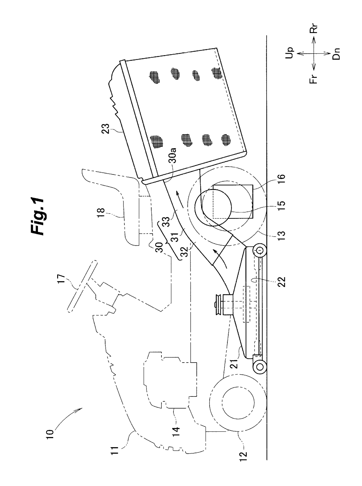
[0018]The directions used in the following description are based on the view of an operator riding the mower.

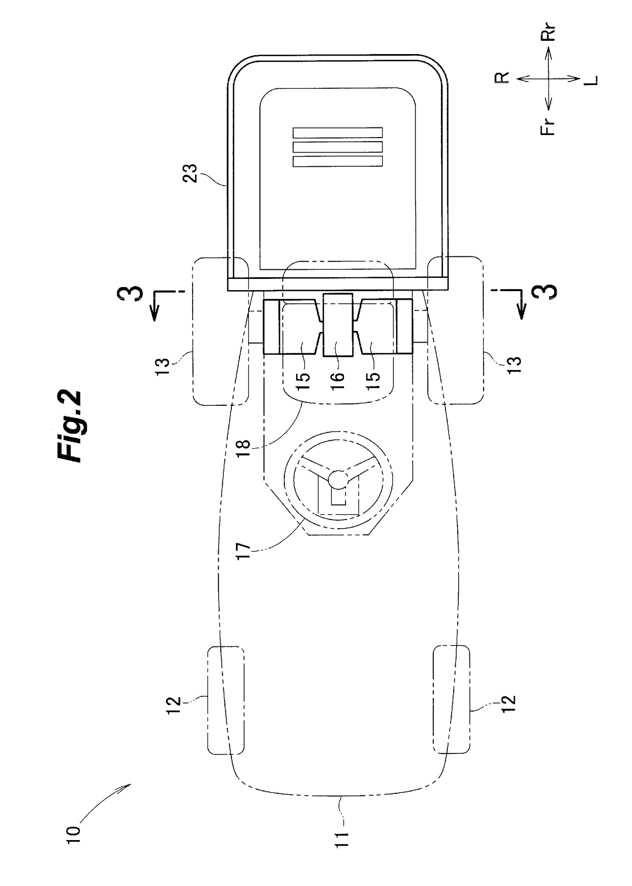
[0019]Referring to FIGS. 1 and 2, a lawn mower 10 embodying the present invention is described in the following.

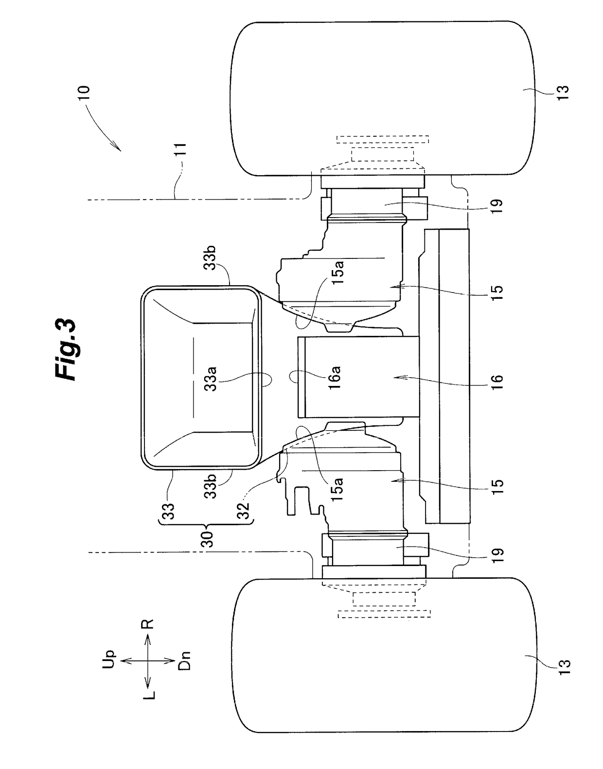
[0020]As best illustrated in FIG. 1, this mower 10 includes a main body 11, a pair of front wheels 12 provided in a front part of the main body 11, a pair of rear wheels 13 provided in a rear part of the main body 11, an internal combustion engine 14 mounted on the main body 11 substantially above the front wheels 12, a pair of electric motors 15 mounted on the main body 11 on the inboard side of the respective rear wheels 13, a fuel tank 16 mounted on the main body 11 substantially centrally between the two electric motors 15, a blade housing 21 having an open lower end and depending from a lower part of the main body 11, a pair of cutting blades 22 supported by an upper part of the housing 21 one next to the other on either side so as to be rotatable in a horizon...


PUM


Abstract

In a mower (10) driven by a pair of electric motors (15) and using an engine (14) for driving a cutter blade (22), a fuel tank (16) for supplying fuel to the engine is positioned in a space surrounded by the electric motors and a chute (30) for forwarding grass clippings to a grass collection bag (23). The chute extends rearward with an upward slant, and is bent in side view in such a manner that a lower part has a steeper incline than an upper part thereof.

Description

TECHNICAL FIELD[0001]The present invention relates to a mower having wheels that are driven by electric motors.BACKGROUND ART[0002]Some of the previously proposed mowers are provided with separate power sources for propelling the mower and driving the cutting blade. JP4189272B discloses such a mower.[0003]The mower disclosed in JP4189272B is a riding mower having a blade housing with an open bottom end, a cutting blade positioned in this blade housing and driven by an internal combustion engine, a pair of rear wheels positioned on either side of the rear end of the housing and a pair of hydraulic motors for driving the respective rear wheels. The mower is thus propelled by the hydraulic motors, and the cutting blade for mowing the grass is driven by the internal combustion engine.[0004]A mower is often fitted with a grass collection bag on the rear end of thereof, and a chute extends from the blade housing to the grass collection bag to forward the cut grass clippings to the grass c...

Claims


Application Information

Patent Timeline
Patent Type & Authority Patents(United States)
IPC IPC(8): A01D34/66A01D69/02A01D43/063A01D101/00
CPCA01D69/02A01D43/063A01D34/667A01D34/66A01D2101/00A01D34/64
Inventor TANABE, SHOTAKURIYAGAWA, KOJIYOSHIMURA, HAJIMEONODERA, SATOSHI
Owner HONDA MOTOR CO LTD
Why Eureka
Try Eureka