Magnetic-suspension planar feed motion device

A feed motion and magnetic levitation technology, which is applied in the direction of holding devices and electrical components using magnetic attraction or thrust, can solve the problems of difficult to meet ultra-precision modern processing equipment, slow dynamic response speed, and difficult to achieve high precision. The effect of fast response, improved smoothness and efficiency, and high drive efficiency

Inactive Publication Date: 2011-09-07
CENT SOUTH UNIV
View PDF2 Cites 14 Cited by
  • Summary
  • Abstract
  • Description
  • Claims
  • Application Information

AI Technical Summary

Problems solved by technology

Due to a series of problems such as friction, backlash, and deformation in the linear motion conversion mechanism, it is difficult to achieve a high level of precision, and the driving efficiency is not high, and the dynamic response speed is slow
In recent years, linear motors have begun to be used in two-dimensional plane positioning devices. However, this positioning device still adopts the superposition mode of single-dimensional motion mechanisms, which is difficult to meet the needs of ultra-precision modern processing equipment for the manufacture of optoelectronics, microelectronics and other products.

Method used


Image

  • Magnetic-suspension planar feed motion device
  • Magnetic-suspension planar feed motion device
  • Magnetic-suspension planar feed motion device

Examples


Embodiment Construction

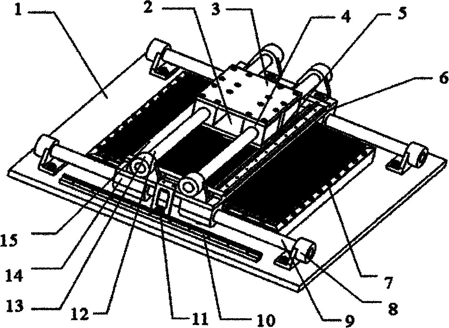
[0016] The present invention will be further described below in conjunction with the accompanying drawings and specific embodiments.

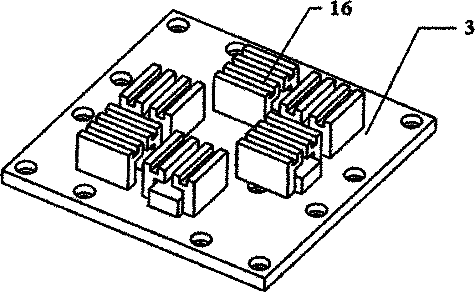
[0017] see figure 1 and figure 2 , the stator platform 1 is equipped with a square protruding array stator 7 uniformly composed of silicon steel sheets, the X-direction cylindrical guide rail 9 is fixed on the X-direction support seat 8, the X-direction support seat 8 is fixedly installed on the stator platform 1, and the X-direction magnetic suspension sliding sleeve The 14 sliding sleeve is installed on the X-direction cylindrical guide rail 9, the X-direction moving platform 15 is installed on the X-direction magnetic suspension sliding sleeve 14, and the support of the X-direction moving platform 15 is realized by two sets of X-direction magnetic suspension sliding sleeves 14 in the X direction. The coil current control in the X-direction magnetic suspension sliding sleeve 14 makes the X-direction moving platform 15 levitate. The Y-direc...


PUM


Abstract

The invention discloses a magnetic-suspension planar feed motion device, which is characterized in that a planar motor is adopted to drive; a stator platform is provided with a square raised head array stator which is formed by silicon sheets evenly; a Y-direction movable platform is provided with two sets of mutually orthorhombic three-phase exciting winding rotors; magnetic-suspension sliding sleeves in two directions are used for supporting a rotor platform respectively; the magnetic-suspension sliding sleeves are arranged on cylindrical guides in the X and Y directions; coil currents in the magnetic-suspension sliding sleeves are controlled to suspend the rotor platform, thus improving the stability and the efficiency of planar motion; excitation voltages are exerted on the three-phase exciting winding rotors by regulation to generate electromagnetic driving power so as to control the planar motion direction of the rotor platform; and grating sensors in two motion directions are utilized to detect motion positions so as to realize accurate planar feed motion. The magnetic-suspension planar feed motion device can be applied to special equipment for manufacturing photoelectrons,micro-electronics and the like, and has wide market prospects.

Description

technical field [0001] The invention relates to a two-coordinate plane motion device, in particular to a magnetic levitation plane feed motion device. Background technique [0002] The traditional planar feed movement device is formed by superimposing two rotating motors in the coordinate direction through the transformation of the linear motion conversion mechanism into a linear motion. Due to a series of problems such as friction, backlash, and deformation in the linear motion conversion mechanism, it is difficult to achieve a high level of precision, and the driving efficiency is not high, and the dynamic response speed is slow. In recent years, linear motors have begun to be used in two-dimensional planar positioning devices. However, this positioning device still adopts the superposition mode of single-dimensional motion mechanisms, which is difficult to meet the needs of ultra-precision modern processing equipment for the manufacture of optoelectronics, microelectronic...

Claims


Application Information

Patent Timeline
Patent Type & Authority Applications(China)
IPC IPC(8): H02N15/00
Inventor 廖平
Owner CENT SOUTH UNIV
Why Eureka
Try Eureka