Vehicle frame structure

a frame structure and vehicle technology, applied in the field of vehicle frame structure, can solve the problems of large bending moment and decrease in the efficiency of transmitting collision load

Active Publication Date: 2018-12-11
TOYOTA JIDOSHA KK
View PDF6 Cites 0 Cited by
  • Summary
  • Abstract
  • Description
  • Claims
  • Application Information

AI Technical Summary

Benefits of technology

[0007]The present disclosure provides a vehicle frame structure at which, even in a case in which a front side member main body portion is inclined toward the vehicle body transverse direction outer side while heading toward the vehicle body front side, collision load may be transmitted well by preventing or suppressing bending of the supporting portion of the rear end portion of the front side member main body portion at the time of a front collision of the vehicle.
[0011]Further, the vehicle body transverse direction intermediate portion of the front side member base portion is joined to the front end portion of the floor under reinforcement, and the rear side first connecting portion is joined to the front end portion of the rocker, and the rear side second connecting portion is joined to the front end portion of the tunnel. Due thereto, the collision load that is inputted to the front side member main body portion is, via the front side member base portion, transmitted and dispersed to the floor under reinforcement, the rocker and the tunnel, respectively. Therefore, the burden of the load that is applied to the front side connecting portion of the front side member base portion is reduced. Further, because the front side member base portion is structured by a single member, it is advantageous in terms of ensuring the supporting rigidity by the front side member base portion, and, in addition, the collision load, that is transmitted from the front side member main body portion to the front side member base portion, can be transmitted directly (without going through another member) to the floor under reinforcement, the rocker and the tunnel.
[0013]Here, the minimum radius of curvature R1 at the curved shape of the first curved wall portion is set to be larger than the minimum radius of curvature at the curved shape of the second curved wall portion. Therefore, at the front side member base portion, the bending rigidity with respect to load, that attempts to bend the front side member base portion toward the first curved wall portion side (the vehicle body transverse direction outer side), is higher than the bending rigidity with respect to the load that attempts to bend the front side member base portion toward the second curved wall portion side (the vehicle body transverse direction inner side). Accordingly, at the time of a front collision, the front side member base portion bending toward the vehicle body transverse direction outer side can be suppressed effectively.
[0015]In accordance with the above-described structure, the radius of curvature R1 of the first curved wall portion can be set to be large, while the rear end portion of the side wall portion at the vehicle body transverse direction outer side of the front side connecting portion and the front end portion of the rear side first connecting portion are connected gently by the first curved wall portion. Therefore, while the ability to transmit load from the front side member base portion to the rocker at the time of a front collision of the vehicle is ensured well, the bending rigidity with respect to load, that attempts to bend the front side member base portion toward the first curved wall portion side (the vehicle body transverse direction outer side), may be ensured well.
[0016]As described above, in accordance with the vehicle frame structure of the present disclosure, even in a case in which a front side member main body portion is disposed at an incline toward a vehicle body transverse direction outer side while heading toward a vehicle body front side, collision load may be transmitted well by preventing or suppressing bending of a supporting portion of the rear end portion of the front side member main body portion at the time of a front collision of the vehicle.

Problems solved by technology

However, in such a structure, at the time of a front collision of the vehicle, a large bending moment arises, and it is easy for the supporting portion of the rear end portion of the front side member main body portion to bend toward the vehicle body transverse direction outer side.
Further, if the supporting portion of the rear end portion of the front side member main body portion bends, the efficiency of transmitting the collision load decreases.

Method used


Image

  • Vehicle frame structure
  • Vehicle frame structure
  • Vehicle frame structure

Examples


Embodiment Construction

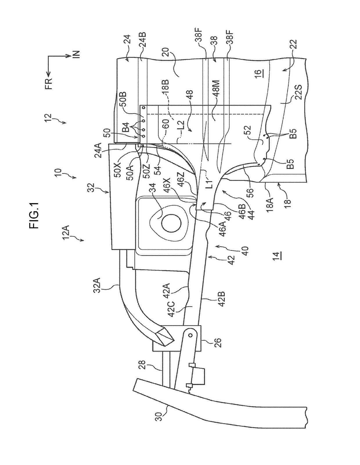
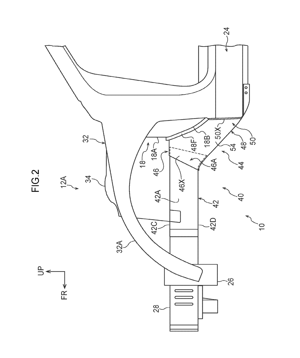
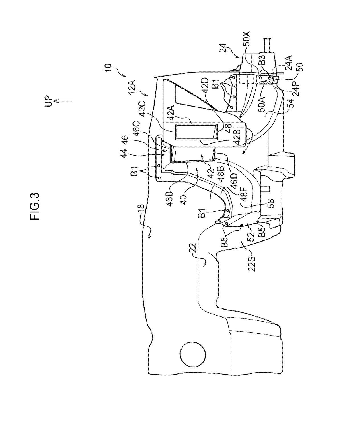
[0021]A vehicle frame structure relating to an embodiment of the present disclosure is described by using FIG. 1 through FIG. 3. Note that arrow FR that is illustrated appropriately in these drawings indicates the vehicle body front side, arrow UP indicates the vehicle body upper side, and arrow IN indicates the vehicle body transverse direction inner side. Further, when description is given hereinafter by merely using longitudinal, vertical and left-right directions, they mean the longitudinal of the vehicle body longitudinal direction, the vertical of the vehicle body vertical direction, and the left and the right when facing in the vehicle advancing direction, unless otherwise indicated.

[0022]A portion of the vehicle body left side of an automobile (a vehicle) 12, to which a vehicle frame structure 10 relating to the present embodiment is applied, is illustrated in a bottom view in FIG. 1. Note that illustration of the vehicle body right side is omitted from FIG. 1, but the vehic...


PUM


Abstract

The present disclosure provides a vehicle frame structure including a front side member base portion in which a rear end portion of an outer-side side wall portion of a front side connecting portion that is joined to the front side member main body portion, and a front end flange portion of a rear side first connecting portion that is joined to a rocker, are connected by a first curved wall portion. Further, a rear end portion of an inner-side side wall portion of the front side connecting portion, and a front end portion of a rear side second connecting portion that is joined to a tunnel, are connected by a second curved wall portion. A minimum radius curvature at a curve of the first curved wall portion is set to be larger than a minimum radius curvature at a curve of the second curved wall portion.

Description

CROSS-REFERENCE TO RELATED APPLICATION[0001]This application claims priority under 35 USC 119 from Japanese Patent Application No. 2015-195808 filed on Oct. 1, 2015, the disclosure of which is incorporated by reference herein.BACKGROUND[0002]Technical Field[0003]The present disclosure relates to a vehicle frame structure.[0004]Related Art[0005]Techniques of dispersing and transmitting collision load that is inputted to a front side member at the time of a front collision of a vehicle are known (see, for example, International Publication No. 2011 / 148747 and Japanese Patent Application Laid-Open (JP-A) No. 2013-136362).[0006]There are cases in which the front side member main body, that is disposed at the side portion of the vehicle body front portion, is inclined toward the vehicle body transverse direction outer side while heading toward the vehicle body front side, from the standpoint of addressing a collision that is such that the automobile front-collides with a collision object...

Claims


Application Information

Patent Timeline
Patent Type & Authority Patents(United States)
IPC IPC(8): B62D21/15B62D25/08
CPCB62D21/155B62D25/08B62D21/152B62D25/082
Inventor SASAKI, TAKASHI
Owner TOYOTA JIDOSHA KK
Why Eureka
Try Eureka