Differential device

a technology of differential device and lubricant oil, which is applied in the direction of gearing details, mechanical equipment, gearing, etc., can solve the problems of insufficient lubricant oil supply at and the sliding portion of the pinion and the meshing portion of the pinion and the side gear is likely to have a shortage of lubricant oil supply, so as to achieve the effect of reducing the width

Active Publication Date: 2017-08-22
MUSA PRECISION IND CO LTD
View PDF21 Cites 1 Cited by
  • Summary
  • Abstract
  • Description
  • Claims
  • Application Information

AI Technical Summary

Benefits of technology

[0008]According to the first characteristic, the pair of side gears each include: the shaft portion connected to the corresponding one of the output shafts; and the intermediate wall portion integrally connecting the shaft portion and the tooth portion separated outward from the shaft portion in the radial direction of the input member and being formed in the flat shape. Thus, the diameter of each side gear can be made sufficiently larger than that of the pinion, so that the number of teeth of the side gear can be set sufficiently larger than the number of teeth of the pinion. This makes it possible to reduce load burden to the pinion support portion while torque is being transmitted from the pinion to the side gears, and thus to decrease an effective diameter of the pinion support portion, and accordingly a width of the pinion in the axial direction. Therefore, in combination with an effect of the flatness of the intermediate wall portions, the above-described decrease can contribute to a reduction of the width of the differential device in the axial direction. Furthermore, even if the tooth portions of the side gears are placed farther from the output shafts in the radial direction due to an increase in the diameter of the side gears as described above, the through oil passage is formed in the intermediate wall portion of at least one side gear, the both ends of the through oil passage being respectively opened in the inner side surface and the outer side surface of the intermediate wall portion. Thus, lubricant oil can flow from the outer side surface side into the inner side surface side of the side gear through the through oil passage, and the lubricant oil flowing into the inner side surface side can be efficiently supplied to the tooth portion in the outer periphery of the side gear, accordingly meshing portions of the side gear and the pinion, using centrifugal force. Thereby, even in the case where the tooth portions of the side gears are placed farther from the output shafts due to an increase in the diameter of the side gears, or even under severe driving conditions with high-speed rotation of the pinion, the lubricant oil can be sufficiently supplied to the meshing portions of the pinion and the side gears and a sliding portion of the pinion. Accordingly, seizure in the meshing portions and the sliding portion can be prevented effectively.
[0010]According to the second characteristic, the differential device further comprises: the cover portion including the side wall portion which covers the outer side surface of at least one side gear and connected to the input member so as to rotate integrally with the input member; and the washer installed between the inner side surface of the side wall portion and the outer side surface of the side gear. The relative positions of the washer and the through oil passage are set such that at least the inner peripheral portion of the washer faces the opening portion of the through oil passage opened to the outer side surface of the intermediate wall portion. Thus, the washer inhibits the lubricant oil from flowing outward in the radial direction along a clearance between the inner side surface of the cover portion and the outer side surface of the side gear due to the centrifugal force, and thereby it is possible to guide the lubricant oil from the inner periphery side of the washer via the through oil passage toward the inner side of the side gear. This makes it possible to increase the amount of lubricant oil which passes through the through oil passage and flows toward the tooth portion in the outer periphery of the side gear along the inner side surface of the side gear, and accordingly to enhance an effect of lubricating the meshing portions and the like. Moreover, since the washer serves also as oil guiding means for guiding the lubricant oil to the through oil passage, the structure can be simplified and thereby it is possible to contribute to cost reduction.
[0014]According to the fourth characteristic, the side wall portion of the cover portion includes the lightening portion exposing the outer side surface of the side gear, and the oil guide groove is provided in a recess shape in the inner side surface of the side wall portion, the oil guide groove being capable of guiding the flow of lubricant oil from the peripheral edge of the lightening portion toward the washer and the through oil passage during the rotation of the input member. Thus, due to an oil guiding effect of the oil guide groove, the flow of the lubricant oil from the peripheral edge of the lightening portion toward the washer and the through oil passage can be efficiently guided using the rotation of the input member. Accordingly, an effect of lubricating the washer is enhanced. In addition, the amount of lubricant oil flowing through the through oil passage toward the tooth portions in the outer peripheries of the side gears can be more effectively increased, and an effect of lubricating the meshing portions and the like can be further enhanced.
[0018]According to the fifth characteristic, the pair of output gears each include: the shaft portion connected to the corresponding one of the output shafts; and the intermediate wall portion integrally connecting the shaft portion and the tooth portion separated outward from the shaft portion in the radial direction of the input member and being formed in the flat shape. Thus, the diameter of each output gear can be made sufficiently larger than that of the differential gear, so that the number of teeth of the output gear can be set sufficiently larger than the number of teeth of the differential gear. This makes it possible to reduce load burden to the differential gear support portion while torque is being transmitted from the differential gear to the output gears, and thus to decrease an effective diameter of the differential gear support portion, and accordingly a width of the differential gear in the axial direction. Therefore, in combination with an effect of the flatness of the intermediate wall portions, the above-described decrease can contribute to a reduction of the width of the differential device in the axial direction. Furthermore, even if the tooth portions of the output gears are placed farther from the output shafts in the radial direction due to an increase in the diameter of the output gears as described above, the through oil passage is formed in the intermediate wall portion of at least one output gear, the both ends of the through oil passage being respectively opened in the inner side surface and the outer side surface of the intermediate wall portion. Thus, lubricant oil can flow from the outer side surface side into the inner side surface side of the output gear through the through oil passage, and the lubricant oil flowing into the inner side surface side can be efficiently supplied to the tooth portion in the outer periphery of the output gear, accordingly meshing portions of the output gear and the differential gear, using centrifugal force. Thereby, even in the case where the tooth portions of the output gears are placed farther from the output shafts due to an increase in the diameter of the output gears, or even under severe driving conditions with high-speed rotation of the differential gear, the lubricant oil can be sufficiently supplied to the meshing portions of the differential gear and the output gears and a sliding portion of the differential gear. Accordingly, seizure in the meshing portions and the sliding portion can be prevented effectively. Moreover, according to the fifth characteristic, the differential device as a whole can be sufficiently reduced in width in the axial direction of the output shafts while securing the strength (for example, the static torsion load strength) and the maximum amount of torque transmission at approximately the same levels as the conventional differential device. Accordingly, the differential device can be easily incorporated in a transmission system, which is under many layout restrictions around the differential device, with great freedom and no specific difficulties, and is therefore advantageous in reducing the size of the transmission system.
[0021]According to the sixth and seventh characteristics, the differential device can be more sufficiently reduced in width in the axial direction of the output shafts while securing the strength (for example, the static torsion load strength) and the maximum amount of torque transmission at approximately the same levels as the conventional differential device.

Problems solved by technology

However, the conventional differential device, cannot efficiently collect and reserve a large amount of lubricant oil at the meshing portions of the pinions and the side gears.
For this reason, the sliding portions of the pinions and the meshing portions of the pinions and the side gears are likely to have shortage of lubricant oil supply, for example, in a case where the meshing portions are placed farther from the output shafts due to an increase in the diameter of the side gears, or under severe driving conditions such as high-speed rotation of the pinions.

Method used


Image

  • Differential device
  • Differential device
  • Differential device

Examples


Embodiment Construction

[0039]Embodiments of the present invention will be hereinbelow described based on preferred examples of the present invention which are shown in the attached drawings.

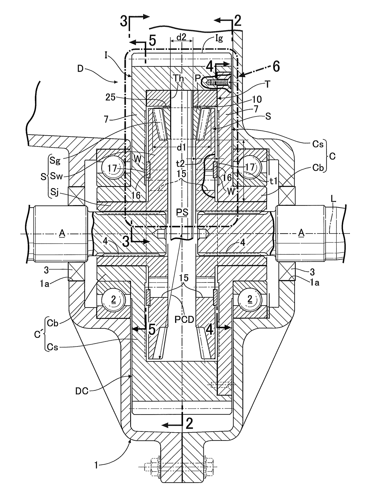
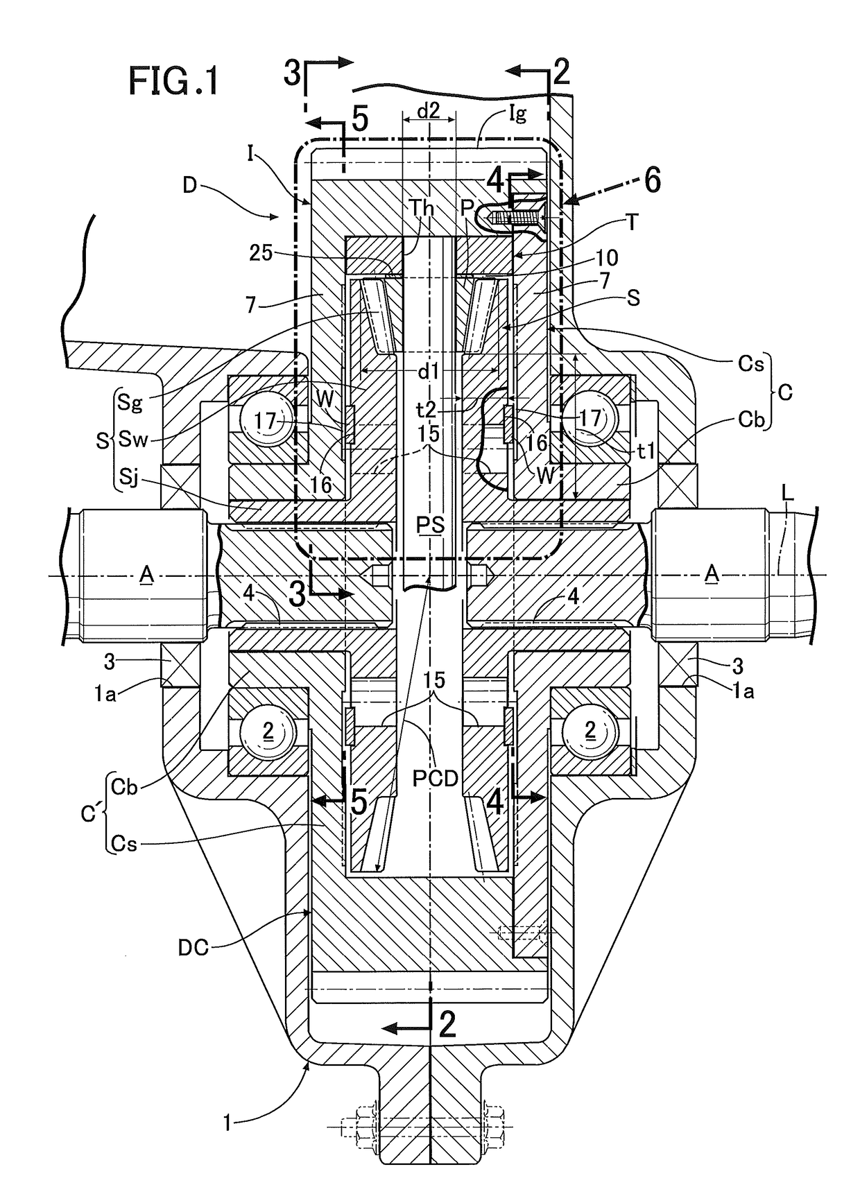
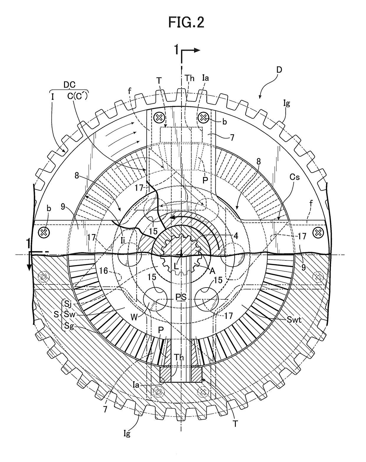
[0040]First of all, descriptions will be provided for a first embodiment of the present invention illustrated in FIGS. 1 to 7. A differential device D drives a pair of left and right axles while allowing their differential rotation by distributively transmitting, to a pair of left and right output shafts A, rotational driving force which is transmitted from an engine (not illustrated) mounted on an automobile, the pair of left and right output shafts A being continuous to the pair of left and right axles. The differential device D is housed and supported, for example, inside a transmission case 1 disposed beside the engine in a front portion of a vehicle body.

[0041]The differential mechanism D includes: a plurality of pinions (differential gears) P; a pinion shaft PS as a pinion support portion (a differential gear sup...


PUM


Abstract

In a differential device, even when tooth portions of side gears are placed farther from output shafts due to increase in diameter of the side gears or even when a pinion rotates at high speed, seizure in meshing portions of the pinion and the side gears and a sliding portion of the pinion is prevented effectively. The side gears each include a shaft portion connected to corresponding one of the output shafts, and a flat intermediate wall portion integrally connecting the shaft portion and the tooth portion of the side gear separated outward from the shaft portion in a radial direction of an input member. A through oil passage is formed in the intermediate wall portion of at least one side gear, both ends of the through oil passage being respectively opened in inner and outer side surfaces of the intermediate wall portion.

Description

BACKGROUND OF THE INVENTION[0001]Field of the Invention[0002]The present invention relates to an improvement of a differential device, particularly the differential device which distributively transmits rotational force of an input member to a pair of output shafts via a pair of side gears (output gears), the input member supporting a pinion support portion (a differential gear support portion) that supports a pinion (a differential gear) and being rotatable together with the pinion support portion, the side gears each having a tooth portion in mesh with a pinion in an outer peripheral portion of each of the side gears.[0003]Description of the Related Art[0004]Conventionally, such a differential device has been publicly known as described in Japanese Patent Application Laid-open No. 2008-89147, for example. The conventional differential device is configured to supply lubricant oil to sliding portions of pinions and meshing portions of the pinions and side gears via clearances betwee...

Claims


Application Information

Patent Timeline
Patent Type & Authority Patents(United States)
IPC IPC(8): F16H57/04F16H48/08
CPCF16H57/0483F16H48/08F16H57/043F16H57/0427
Inventor MORI, HIROYUKINISHIMURA, NAOYA
Owner MUSA PRECISION IND CO LTD
Why Eureka
Try Eureka