
Differential device

a technology of differential devices and components, applied in the direction of gearing details, mechanical equipment, gearing, etc., can solve the problems of concentrating excessively on the outermost peripheral end portions, and reducing the thickness and weight of input members. , to achieve the effect of simple structur

Inactive Publication Date: 2016-12-22
MUSA PRECISION IND CO LTD
View PDF11 Cites 1 Cited by
  • Summary
  • Abstract
  • Description
  • Claims
  • Application Information

AI Technical Summary

Benefits of technology

The present invention provides a differential device with a simple structure to solve the problem of excessive load concentration on the outer peripheral end of the output gear. By extending the outer peripheral end of the washer abutting surface of the output gear and incorporating an intermediate wall portion between the shaft portion and the tooth portion, the load burden on the tooth portion is reduced, allowing for a reduction in the thickness and weight of the input member and the tooth portion in the outer periPR of the output gear. The differential device can also be integrated into a transmission system with greater freedom and without specific difficulties. The technical effects of this invention are a reduction in size and weight of the differential device, increased load distribution, and improved strength and torque transmission capabilities.

Problems solved by technology

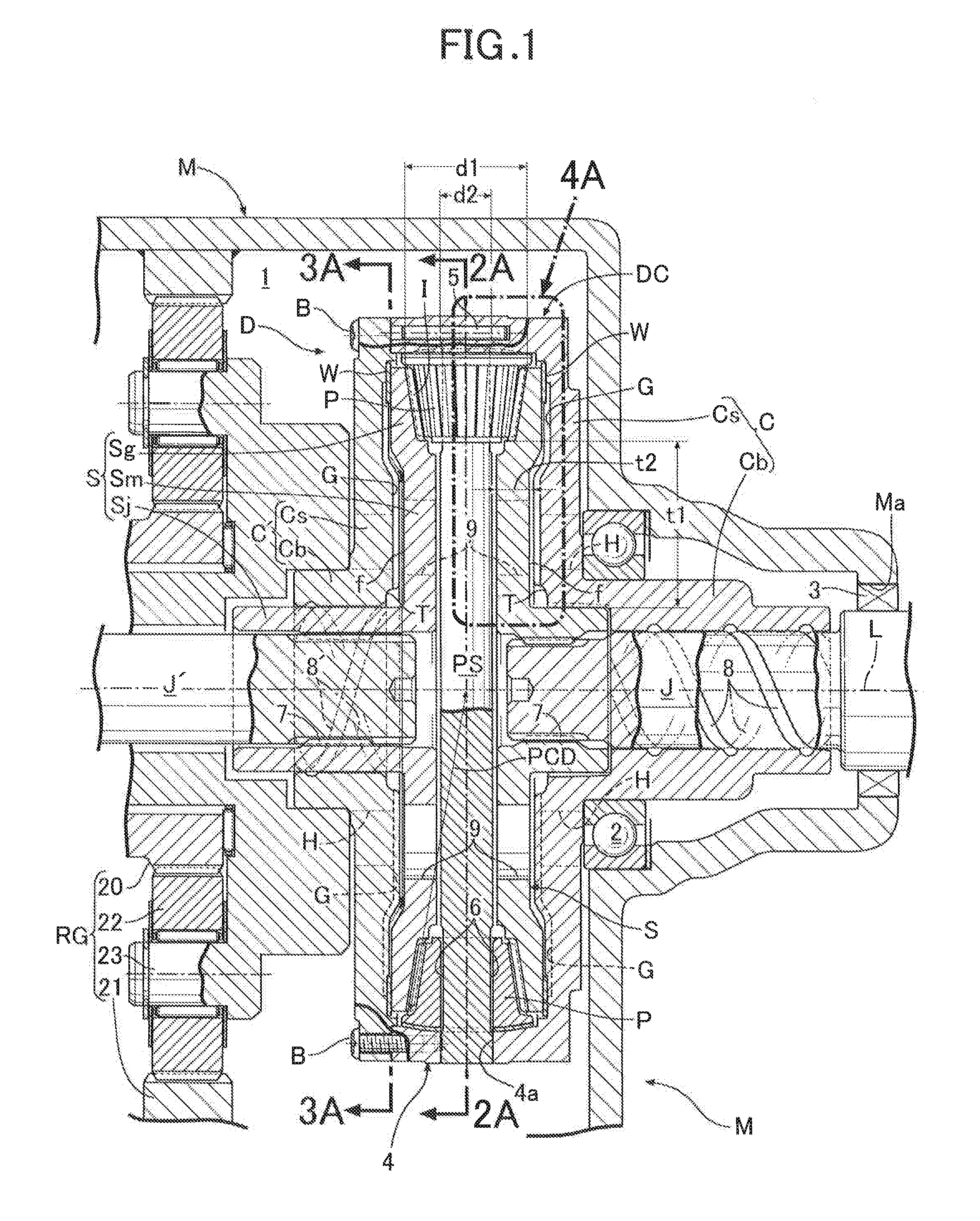
Accordingly, large thrust reaction force, which is transmitted from the differential gears via tooth portions in outer peripheries of the output gears, excessively concentrates on particularly outermost peripheral end portions of the washer abutting surfaces of the output gears.
As a result, even though outer peripheral portions of the washers are extended further radially outward than the washer abutting surfaces so as to distribute load in washer receiving portions of the input member, load burden is locally large in the washer receiving portions.
This is a disadvantage in reducing the thickness and weight of the input member.
Furthermore, such problems are disadvantageous for a differential device whose, particularly, input member and output gears are required to be reduced in thickness and weight, such as, for example, a differential device which is made thinner in an axial direction of the output gears of the differential device by making the diameter of the output gears sufficiently larger than that of the differential gears such that the output gears can have a sufficiently larger number of teeth than that of the differential gears.

Method used


Image

  • Differential device
  • Differential device
  • Differential device

Examples


Embodiment Construction

[0035]Embodiments of the present invention will be described below based on the attached drawings.

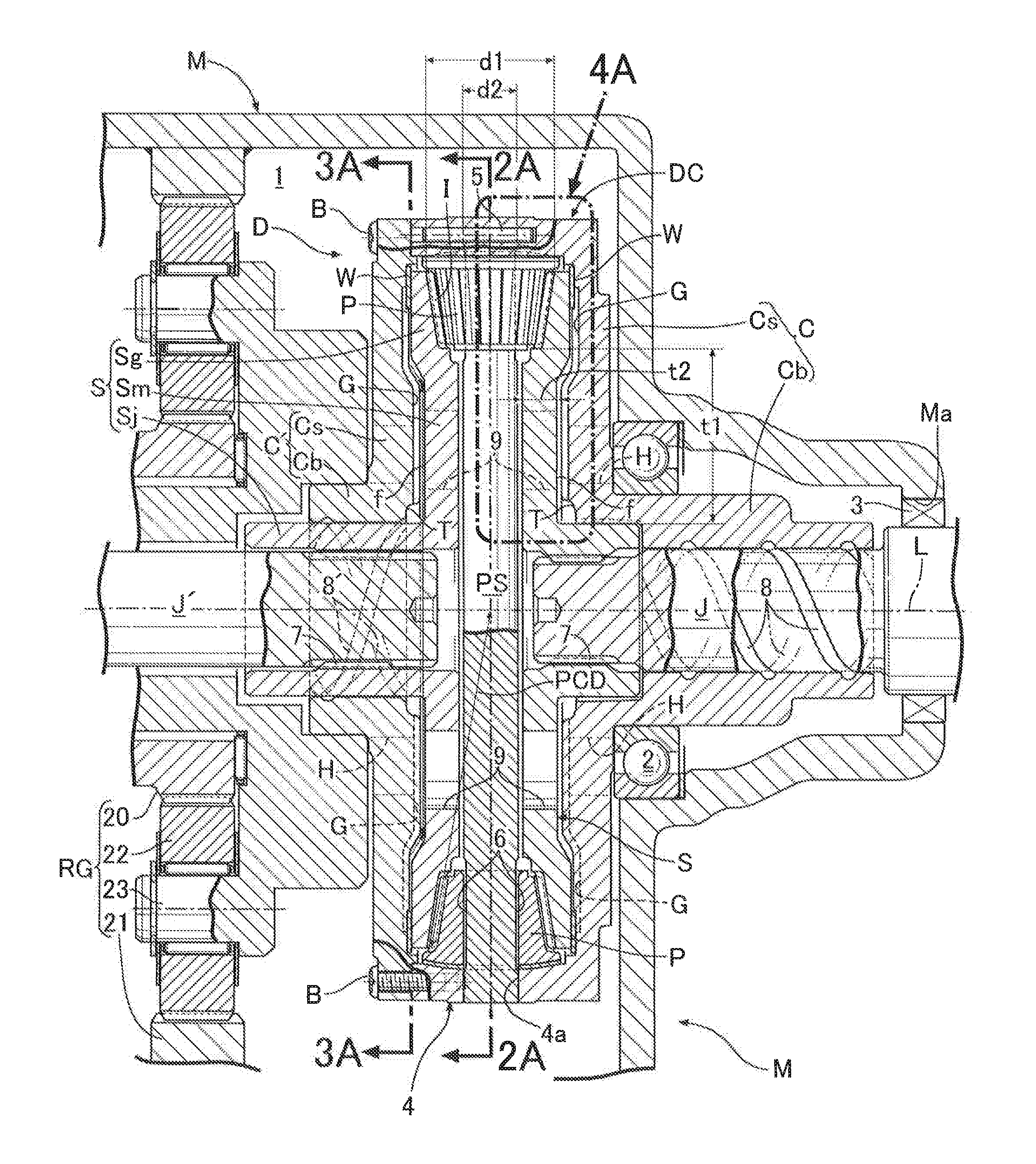
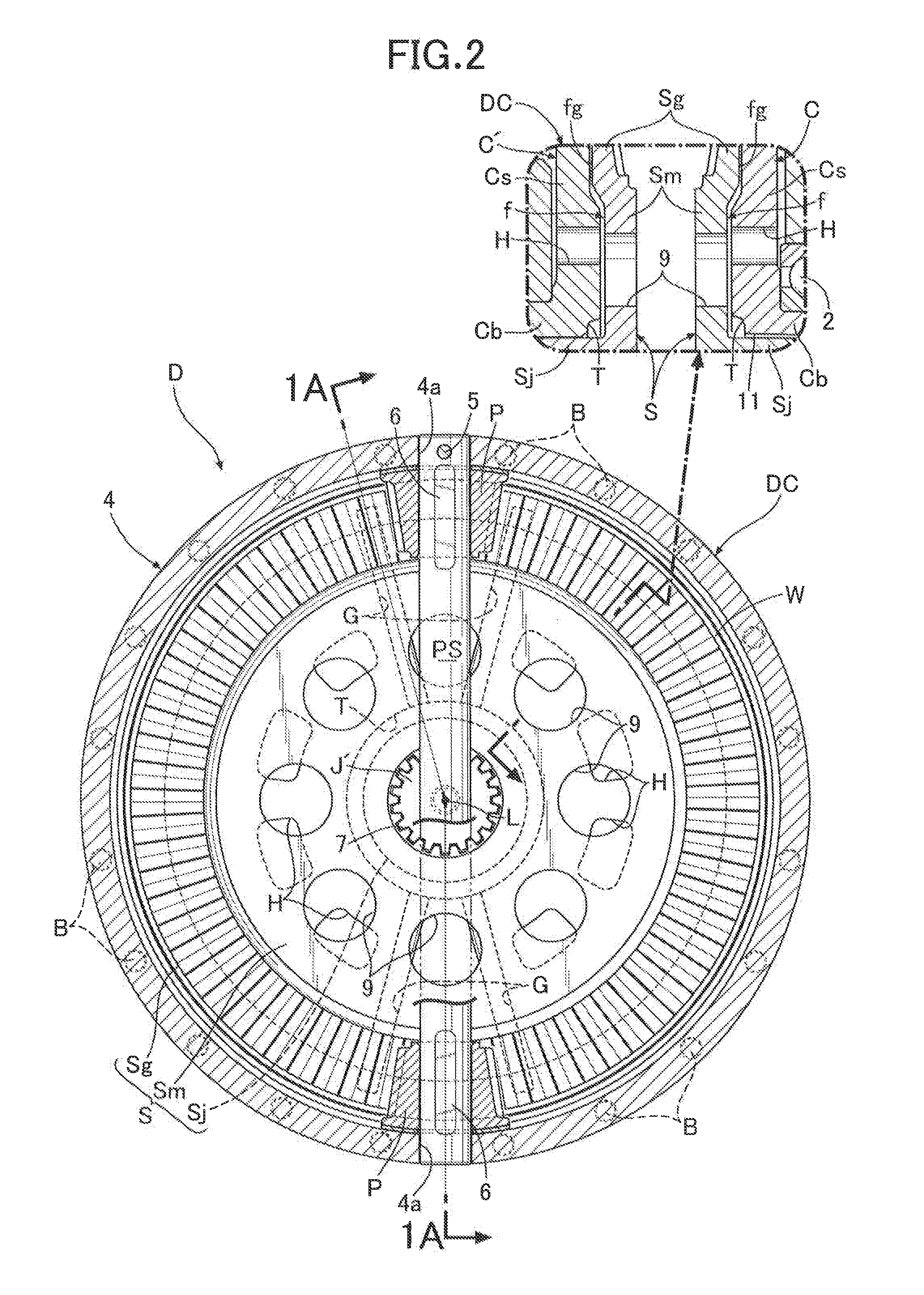
[0036]First of all, referring to FIGS. 1 to 4, a first embodiment of the present invention will be described. In FIG. 1, a differential device D is connected to an engine (not illustrated) as a power source mounted on an automobile via a speed reduction gear mechanism RG. The differential device D drives a pair of axles arranged in parallel in a vehicle width direction while allowing differential rotation between the pair of axles by distributively transmitting to output shafts J, J′ rotational force which is transmitted from the engine to a differential case DC via the speed reduction gear mechanism RG, the output shafts J, J′ being continuous respectively to the pair of axles. The differential device D is housed together with the speed reduction gear mechanism RG in, for example, a transmission case M placed beside the engine in a front portion of a vehicle body, in a way that the dif...


PUM


Abstract

A differential device includes: an input member inputted with driving force; a differential gear supported in the input member and capable of rotating relative to the input member and revolving around rotation center of the input member with rotation of the input member; paired output gears each including in an outer peripheral portion thereof tooth portion meshing with the differential gear; and a washer interposed between the input member and back surface of each output gear. A washer abutting surface in the back surface of the output gear abuts against the washer and has an outermost peripheral end thereof located at the same position as or outward of outermost peripheral end of meshing portion between the output and differential gears in radial direction of output gear. An outer peripheral end portion of the washer extends radially outward than the washer abutting surface.

Description

BACKGROUND OF THE INVENTION[0001]Field of the Invention[0002]The present invention relates to a differential device which is provided in a vehicle such as, for example, an automobile.[0003]Description of the Related Art[0004]Japanese Patent No. 4828847 has made known a conventional differential device in which a washer is interposed between a back surface of each of output gears and an input member (for example, a differential case).[0005]In the above-mentioned conventional device, a meshing portion between the output gear and a differential gear are located further radially outward than a washer abutting surface, which abuts against the washer, in the back surface of each output gear. Accordingly, large thrust reaction force, which is transmitted from the differential gears via tooth portions in outer peripheries of the output gears, excessively concentrates on particularly outermost peripheral end portions of the washer abutting surfaces of the output gears. As a result, even thou...

Claims


Application Information

Patent Timeline
Patent Type & Authority Applications(United States)
IPC IPC(8): F16H48/40F16H57/04F16H48/08
CPCF16H48/40F16H57/0483F16H48/08F16H48/38F16H57/0428F16H2048/387
Inventor MORI, HIROYUKI
Owner MUSA PRECISION IND CO LTD
Learn More